Product Description
Model Selection
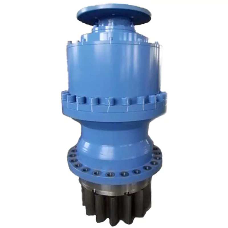
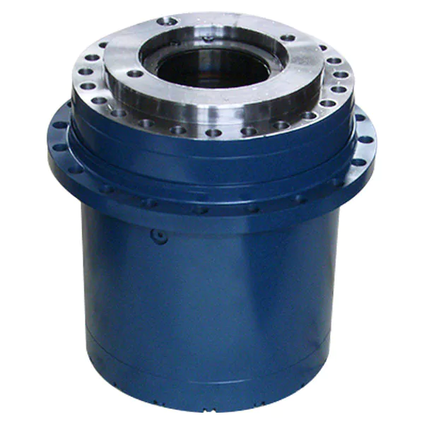
Planetar y gearbox is a kind of reducer with wide versatility. The inner gear adopts low carbon alloy steel carburizing quenching and grinding or nitriding process. Planetary gearbox has the characteristics of small structure size, large output torque, high speed ratio, high efficiency, safe and reliable performance, etc. The inner gear of the planetary gearbox can be divided into spur gear and helical gear.
• Model Selection
Our professional sales representive and technical team will choose the right model and transmission solutions for your usage depend on your specific parameters.
• Drawing Request
If you need more product parameters, catalogues, CAD or 3D drawings, please contact us.
• On Your Need
We can modify standard products or customize them to meet your specific needs.
Range Of Planetary Gearbox
Other Products
Company Profile
/* January 22, 2571 19:08:37 */!function(){function s(e,r){var a,o={};try{e&&e.split(“,”).forEach(function(e,t){e&&(a=e.match(/(.*?):(.*)$/))&&1
| Application: | Motor, Machinery, Marine, Agricultural Machinery |
|---|---|
| Function: | Change Drive Torque, Speed Changing, Speed Reduction |
| Hardness: | Hardened Tooth Surface |
| Installation: | Vertical Type |
| Type: | Planetary Gear Box |
| Size: | 60mm-160mm |
| Samples: |
US$ 100/Piece
1 Piece(Min.Order) | |
|---|
| Customization: |
Available
| Customized Request |
|---|
Concept of Coaxial and Parallel Shaft Arrangements in Planetary Gearboxes
In planetary gearboxes, the arrangement of shafts plays a crucial role in determining the gearbox’s overall structure and functionality. The two common shaft arrangements are coaxial and parallel configurations:
Coaxial Shaft Arrangement: In a coaxial arrangement, the input shaft and output shaft are positioned along the same axis, resulting in a compact and streamlined design. The planetary gears and other components are aligned concentrically around the central axis, allowing for efficient power transmission and reduced space requirements. Coaxial planetary gearboxes are commonly used in applications where space is limited, and a compact form factor is essential. They are often employed in robotics, automotive systems, and aerospace mechanisms.
Parallel Shaft Arrangement: In a parallel arrangement, the input and output shafts are positioned parallel to each other but on different axes. The planetary gears are aligned in a way that allows the power to be transmitted from the input shaft to the output shaft via a combination of meshing gears. This arrangement allows for a larger gear diameter and higher torque transmission capabilities. Parallel planetary gearboxes are often used in applications requiring high torque and heavy-duty performance, such as industrial machinery, construction equipment, and material handling systems.
The choice between coaxial and parallel shaft arrangements depends on the specific requirements of the application. Coaxial configurations are favored for compactness and efficient power transmission, while parallel configurations excel in handling higher torque and heavy loads. Both arrangements offer distinct advantages and are chosen based on factors like available space, torque demands, load characteristics, and overall system design.
Signs of Wear or Damage in Planetary Gearboxes and Recommended Service
Planetary gearboxes, like any mechanical component, can exhibit signs of wear or damage over time. Recognizing these signs is crucial for timely maintenance to prevent further issues. Here are some common signs of wear or damage in planetary gearboxes:
1. Unusual Noise: Excessive noise, grinding, or whining sounds during operation can indicate worn or misaligned gear teeth. Unusual noise is often a clear indicator that something is wrong within the gearbox.
2. Increased Vibration: Excessive vibration or shaking during operation can result from misalignment, damaged bearings, or worn gears. Vibration can lead to further damage if not addressed promptly.
3. Gear Tooth Wear: Inspect gear teeth for signs of wear, pitting, or chipping. These issues can result from improper lubrication, overload, or other operational factors. Damaged gear teeth can affect the gearbox’s efficiency and performance.
4. Oil Leakage: Leakage of gearbox oil or lubricant can indicate a faulty seal or gasket. Oil leakage not only leads to reduced lubrication but can also cause environmental contamination and further damage to the gearbox components.
5. Temperature Increase: A significant rise in operating temperature can suggest increased friction due to wear or inadequate lubrication. Monitoring temperature changes can help identify potential issues early.
6. Reduced Efficiency: If you notice a decrease in performance, such as decreased torque output or inconsistent speed, it could indicate internal damage to the gearbox components.
7. Abnormal Gear Ratios: If the output speed or torque does not match the expected gear ratio, it could be due to gear wear, misalignment, or other issues affecting the gear engagement.
8. Frequent Maintenance Intervals: If you find that you need to service the gearbox more frequently than usual, it could be a sign that the gearbox is experiencing excessive wear or damage.
When to Service: If any of the above signs are observed, it’s important to address them promptly. Regular maintenance checks are also recommended to detect potential issues early and prevent more significant problems. Scheduled maintenance should include inspections, lubrication checks, and replacement of worn or damaged components.
It’s advisable to consult the gearbox manufacturer’s guidelines for recommended service intervals and practices. Regular maintenance can extend the lifespan of the planetary gearbox and ensure it continues to operate efficiently and reliably.
Factors to Consider When Selecting a Planetary Gearbox
Choosing the right planetary gearbox for a specific application involves considering various factors to ensure optimal performance and compatibility. Here are the key factors to keep in mind:
- Load Requirements: Determine the torque and speed requirements of your application. Planetary gearboxes offer different torque and speed ratios, so selecting the appropriate gearbox with the right load capacity is crucial.
- Ratio: Evaluate the gear reduction ratio needed to achieve the desired output speed and torque. Planetary gearboxes come in various gear ratios, allowing you to customize the output characteristics.
- Efficiency: Consider the gearbox’s efficiency, as it affects energy consumption and heat generation. Higher efficiency gearboxes minimize power losses during transmission.
- Size and Compactness: Planetary gearboxes are known for their compact size, but it’s essential to choose a size that fits within the available space while meeting performance requirements.
- Mounting Configuration: Determine how the gearbox will be mounted in your application. Planetary gearboxes can have different mounting options, including flange, shaft, or foot mountings.
- Input and Output Types: Select the appropriate input and output shaft configurations, such as male, female, keyed, splined, or hollow shafts, to ensure compatibility with your equipment.
- Environment: Consider the operating environment, including temperature, humidity, dust, and potential exposure to chemicals. Choose a gearbox with appropriate seals and materials to withstand the conditions.
- Accuracy: Some applications require precise motion control. If accuracy is essential, choose a gearbox with minimal backlash and high gear mesh quality.
- Service Life and Reliability: Evaluate the gearbox’s expected service life and reliability based on the manufacturer’s specifications. Choose a reputable manufacturer known for producing reliable products.
- Backlash: Backlash is the play between gears that can affect positioning accuracy. Depending on your application, you might need a gearbox with low backlash or a method to compensate for it.
- Budget: Consider your budget constraints while balancing performance requirements. Sometimes, investing in a higher-quality gearbox upfront can lead to long-term cost savings through reduced maintenance and downtime.
By carefully considering these factors and consulting with gearbox manufacturers or experts, you can select a planetary gearbox that best meets the unique demands of your application.


editor by CX 2024-05-10
China OEM ZD AC/DC Brush Or Brushless Machine Motor Planetary Gearbox with Wide Versatility components of gearbox
Product Description
Model Selection
ZD Leader has a wide range of micro motor production lines in the industry, including DC Motor, AC Motor, Brushless Motor, Planetary Gear Motor, Drum Motor, Planetary Gearbox, RV Reducer and Harmonic Gearbox etc. Through technical innovation and customization, we help you create outstanding application systems and provide flexible solutions for various industrial automation situations.
• Model Selection
Our professional sales representive and technical team will choose the right model and transmission solutions for your usage depend on your specific parameters.
• Drawing Request
If you need more product parameters, catalogues, CAD or 3D drawings, please contact us.
• On Your Need
We can modify standard products or customize them to meet your specific needs.
Product Parameters
Type Of RV Reducer
Application Of RV Reeducer
Precision Cycloidal Gearbox is widely used in industrial machinery fields such as machine tool, robot arm, industrial robot, die-casting feeding machine, manipulator for punching machine, AGV driver, bottle-making machine, UV Printer and etc.
Other Products
Company Profile
| Application: | Motor, Machinery |
|---|---|
| Hardness: | Hardened Tooth Surface |
| Installation: | Vertical Type |
| Layout: | Coaxial |
| Gear Shape: | Conical – Cylindrical Gear |
| Step: | Three-Step |
| Customization: |
Available
| Customized Request |
|---|
Challenges in Achieving High Gear Ratios with Compactness in Planetary Gearboxes
Designing planetary gearboxes with high gear ratios while maintaining a compact form factor poses several challenges due to the intricate arrangement of gears and the need to balance various factors:
Space Constraints: Increasing the gear ratio typically requires adding more planetary stages, resulting in additional gears and components. However, limited available space can make it challenging to fit these additional components without compromising the compactness of the gearbox.
Efficiency: As the number of planetary stages increases to achieve higher gear ratios, there can be a trade-off in terms of efficiency. Additional gear meshings and friction losses can lead to decreased overall efficiency, impacting the gearbox’s performance.
Load Distribution: The distribution of loads across multiple stages becomes critical when designing high gear ratio planetary gearboxes. Proper load distribution ensures that each stage shares the load proportionally, preventing premature wear and ensuring reliable operation.
Bearing Arrangement: Accommodating multiple stages of planetary gears requires an effective bearing arrangement to support the rotating components. Improper bearing selection or arrangement can lead to increased friction, reduced efficiency, and potential failures.
Manufacturing Tolerances: Achieving high gear ratios demands tight manufacturing tolerances to ensure accurate gear tooth profiles and precise gear meshing. Any deviations can result in noise, vibration, and reduced performance.
Lubrication: Adequate lubrication becomes crucial in maintaining smooth operation and reducing friction as gear ratios increase. However, proper lubrication distribution across multiple stages can be challenging, impacting efficiency and longevity.
Noise and Vibration: The complexity of high gear ratio planetary gearboxes can lead to increased noise and vibration levels due to the higher number of gear meshing interactions. Managing noise and vibration becomes essential for ensuring acceptable performance and user comfort.
To address these challenges, engineers employ advanced design techniques, high-precision manufacturing processes, specialized materials, innovative bearing arrangements, and optimized lubrication strategies. Achieving the right balance between high gear ratios and compactness involves careful consideration of these factors to ensure the gearbox’s reliability, efficiency, and performance.
Enhancing Wind Turbine System Performance with Planetary Gearboxes
Planetary gearboxes play a crucial role in enhancing the performance and efficiency of wind turbine systems. Here’s how they contribute:
1. Speed Conversion: Wind turbines operate optimally at specific rotational speeds to generate electricity efficiently. Planetary gearboxes allow for speed conversion between the low rotational speed of the wind turbine rotor and the higher speed required by the generator. This speed adaptation ensures the generator operates at its peak efficiency, resulting in maximum power generation.
2. Torque Amplification: Wind turbine blades may experience varying wind speeds, which result in fluctuating torque loads. Planetary gearboxes can amplify the torque generated by the rotor blades before transmitting it to the generator. This torque multiplication helps maintain stable generator operation even during wind speed variations, improving overall energy production.
3. Compact Design: Wind turbines are often installed in locations with limited space, such as offshore platforms or densely populated areas. Planetary gearboxes offer a compact design, allowing for efficient power transmission within a small footprint. This compactness is vital for accommodating gearboxes in the limited nacelle space of the wind turbine.
4. Load Distribution: Wind turbines are subjected to varying wind conditions, including gusts and turbulence. Planetary gearboxes distribute the load evenly among multiple planet gears, reducing stress and wear on individual components. This balanced load distribution improves gearbox durability and reliability.
5. Efficiency Optimization: Planetary gearboxes are known for their high efficiency due to their parallel axis arrangement and multiple gear stages. The efficient power transmission minimizes energy losses within the gearbox, resulting in more power being converted from wind energy to electricity.
6. Maintenance and Reliability: The robust construction of planetary gearboxes contributes to their durability and longevity. Wind turbines often operate in challenging environments, and the reliability of the gearbox is crucial for minimizing maintenance and downtime. Planetary gearboxes’ low maintenance requirements and ability to handle varying loads contribute to the overall reliability of wind turbine systems.
7. Variable Speed Control: Some wind turbines use variable-speed operation to optimize power generation across a range of wind speeds. Planetary gearboxes can facilitate variable speed control by adjusting the gear ratio to match the wind conditions. This flexibility improves energy capture and reduces stress on turbine components.
8. Adaptation to Turbine Size: Planetary gearboxes are available in various sizes and gear ratios, making them adaptable to different turbine sizes and power outputs. This versatility allows wind turbine manufacturers to select gearboxes that align with specific project requirements.
Overall, planetary gearboxes play a pivotal role in optimizing the performance, efficiency, and reliability of wind turbine systems. Their ability to convert speed, amplify torque, and distribute loads makes them a key component in harnessing wind energy for clean and sustainable electricity generation.
Design Principles and Functions of Planetary Gearboxes
Planetary gearboxes, also known as epicyclic gearboxes, are a type of gearbox that consists of one or more planet gears that revolve around a central sun gear, all contained within an outer ring gear. The design principles and functions of planetary gearboxes are based on this unique arrangement:
- Sun Gear: The sun gear is positioned at the center and is connected to the input shaft. It transmits power from the input source to the planetary gears.
- Planet Gears: Planet gears are small gears that rotate around the sun gear. They are typically mounted on a carrier, which is connected to the output shaft. The interaction between the planet gears and the sun gear creates both speed reduction and torque amplification.
- Ring Gear: The outer ring gear is stationary and surrounds the planet gears. The teeth of the planet gears mesh with the teeth of the ring gear. The ring gear serves as the housing for the planet gears and provides a fixed outer reference point.
- Function: Planetary gearboxes offer various gear reduction ratios by altering the arrangement of the input, output, and planet gears. Depending on the configuration, the sun gear, planet gears, or ring gear can serve as the input, output, or stationary element. This flexibility allows planetary gearboxes to achieve different torque and speed combinations.
- Gear Reduction: In a planetary gearbox, the planet gears rotate while also revolving around the sun gear. This double motion creates multiple gear meshing points, distributing the load and enhancing torque transmission. The output shaft, connected to the planet carrier, rotates at a lower speed and higher torque than the input shaft.
- Torque Amplification: Due to the multiple points of contact between the planet gears and the sun gear, planetary gearboxes can achieve torque amplification. The arrangement of gears allows for load sharing and distribution, leading to efficient torque transmission.
- Compact Size: The compact design of planetary gearboxes, achieved by stacking the gears concentrically, makes them suitable for applications where space is limited.
- Multiple Stages: Planetary gearboxes can be designed with multiple stages, where the output of one stage becomes the input of the next. This arrangement allows for high gear reduction ratios while maintaining a compact size.
- Controlled Motion: By controlling the arrangement of the gears and their rotation, planetary gearboxes can provide different motion outputs, including forward, reverse, and even variable speeds.
Overall, the design principles of planetary gearboxes allow them to provide efficient torque transmission, compact size, high gear reduction, and versatile motion control, making them well-suited for various applications in industries such as automotive, robotics, aerospace, and more.
editor by CX 2023-10-21
China high quality ZD High-Speed Ratio 2-3 Stages Vertical Type High-Precision Machine Motor Planetary Gearbox cvt gearbox
Product Description
Model Selection
ZD Leader has a wide range of micro motor production lines in the industry, including DC Motor, AC Motor, Brushless Motor, Planetary Gear Motor, Drum Motor, Planetary Gearbox, RV Reducer and Harmonic Gearbox etc. Through technical innovation and customization, we help you create outstanding application systems and provide flexible solutions for various industrial automation situations.
• Model Selection
Our professional sales representive and technical team will choose the right model and transmission solutions for your usage depend on your specific parameters.
• Drawing Request
If you need more product parameters, catalogues, CAD or 3D drawings, please contact us.
• On Your Need
We can modify standard products or customize them to meet your specific needs.
Product Parameters
Type Of RV Reducer
Application Of RV Reeducer
Precision Cycloidal Gearbox is widely used in industrial machinery fields such as machine tool, robot arm, industrial robot, die-casting feeding machine, manipulator for punching machine, AGV driver, bottle-making machine, UV Printer and etc.
Other Products
Company Profile
| Application: | Motor, Machinery |
|---|---|
| Hardness: | Hardened Tooth Surface |
| Installation: | Vertical Type |
| Layout: | Coaxial |
| Gear Shape: | Conical – Cylindrical Gear |
| Step: | Three-Step |
| Customization: |
Available
| Customized Request |
|---|
Contribution of Planetary Gearboxes to Conveyor Belt Efficiency in Mining Operations
Planetary gearboxes play a significant role in enhancing the efficiency of conveyor belts used in mining operations:
- High Torque Capability: Planetary gearboxes are capable of providing high torque output, which is essential for handling heavy loads of mined materials on conveyor belts.
- Compact Design: The compact nature of planetary gearboxes allows them to be integrated into tight spaces, making them suitable for conveyor systems where space is limited.
- Multi-Stage Design: Planetary gearboxes can achieve high gear ratios through multiple stages of gear reduction. This allows for efficient power transmission from the motor to the conveyor, reducing the load on the motor and increasing overall efficiency.
- Load Distribution: Planetary gearboxes distribute the load across multiple planet gears, which helps in minimizing wear and ensuring longer lifespan of the gearbox.
- Variable Speed Control: By using planetary gearboxes with variable speed capabilities, conveyor belts can be operated at different speeds to match the processing requirements, optimizing material handling and energy consumption.
- Overload Protection: Some planetary gearboxes feature built-in overload protection mechanisms, safeguarding the gearbox and conveyor system from damage due to sudden increases in load.
Overall, planetary gearboxes enhance the efficiency, reliability, and performance of conveyor belts in mining operations by providing the necessary torque, compact design, and precise control needed to transport mined materials effectively.
Impact of Temperature Variations and Environmental Conditions on Planetary Gearbox Performance
The performance of planetary gearboxes can be significantly influenced by temperature variations and environmental conditions. Here’s how these factors impact their operation:
Temperature Variations: Extreme temperature fluctuations can affect the lubrication properties of the gearbox. Cold temperatures can cause the lubricant to thicken, leading to increased friction and reduced efficiency. On the other hand, high temperatures can cause the lubricant to thin out, potentially leading to insufficient lubrication and accelerated wear.
Environmental Contaminants: Planetary gearboxes used in outdoor or industrial environments can be exposed to contaminants such as dust, dirt, moisture, and chemicals. These contaminants can infiltrate the gearbox and degrade the quality of the lubricant. Additionally, abrasive particles can cause wear on gear surfaces, leading to decreased performance and potential damage.
Corrosion: Exposure to moisture, especially in humid or corrosive environments, can lead to corrosion of gearbox components. Corrosion weakens the structural integrity of gears and other components, which can ultimately result in premature failure.
Thermal Expansion: Temperature changes can cause materials to expand and contract. In gearboxes, this can lead to misalignment of gears and improper meshing, causing noise, vibration, and reduced efficiency. Proper consideration of thermal expansion is crucial in gearbox design.
Sealing and Ventilation: To mitigate the impact of temperature and environmental factors, planetary gearboxes need effective sealing to prevent contaminants from entering and to retain the lubricant. Proper ventilation is also essential to prevent pressure build-up inside the gearbox due to temperature changes.
Cooling Systems: In applications where temperature control is critical, cooling systems such as fans or heat exchangers can be incorporated to maintain optimal operating temperatures. This helps prevent overheating and ensures consistent gearbox performance.
Overall, temperature variations and environmental conditions can have a profound impact on the performance and lifespan of planetary gearboxes. Manufacturers and operators need to consider these factors during design, installation, and maintenance to ensure reliable and efficient operation.
Challenges and Solutions for Managing Power Transmission Efficiency in Planetary Gearboxes
Managing power transmission efficiency in planetary gearboxes is crucial to ensure optimal performance and minimize energy losses. Several challenges and solutions are involved in maintaining high efficiency:
1. Gear Meshing Efficiency: The interaction between gears can lead to energy losses due to friction and meshing misalignment. To address this, manufacturers use precision manufacturing techniques to ensure accurate gear meshing and reduce friction. High-quality materials and surface treatments are also employed to minimize wear and friction.
2. Lubrication: Proper lubrication is essential to reduce friction and wear between gear surfaces. Using high-quality lubricants with the appropriate viscosity and additives can enhance power transmission efficiency. Regular maintenance and monitoring of lubrication levels are vital to prevent efficiency losses.
3. Bearing Efficiency: Bearings support the rotating elements of the gearbox and can contribute to energy losses if not properly designed or maintained. Choosing high-quality bearings and ensuring proper alignment and lubrication can mitigate efficiency losses in this area.
4. Bearing Preload: Incorrect bearing preload can lead to increased friction and efficiency losses. Precision assembly and proper adjustment of bearing preload are necessary to optimize power transmission efficiency.
5. Mechanical Losses: Various mechanical losses, such as windage and churning losses, can occur in planetary gearboxes. Designing gearboxes with streamlined shapes and efficient ventilation systems can reduce these losses and enhance overall efficiency.
6. Material Selection: Choosing appropriate materials with high strength and minimal wear characteristics is essential for reducing power losses due to material deformation and wear. Advanced materials and surface coatings can be employed to enhance efficiency.
7. Noise and Vibration: Excessive noise and vibration can indicate energy losses in the form of mechanical inefficiencies. Proper design and precise manufacturing techniques can help minimize noise and vibration, indicating better power transmission efficiency.
8. Efficiency Monitoring: Regular efficiency monitoring through testing and analysis allows engineers to identify potential issues and optimize gearbox performance. This proactive approach ensures that any efficiency losses are promptly addressed.
By addressing these challenges through careful design, material selection, manufacturing techniques, lubrication, and maintenance, engineers can manage power transmission efficiency in planetary gearboxes and achieve high-performance power transmission systems.
editor by CX 2023-10-17
China ZD AC/DC Brush Or Brushless Machine Motor Planetary Gearbox with Wide Versatility planetary gearbox backdrive
Item Description
Design Choice
ZD Leader has a wide range of micro motor manufacturing strains in the market, which includes DC Motor, AC Motor, Brushless Motor, Planetary Equipment Motor, Drum Motor, Planetary Gearbox, RV Reducer and Harmonic Gearbox and so on. By way of technological innovation and customization, we help you generate outstanding application programs and provide versatile options for a variety of industrial automation scenarios.
• Model Selection
Our expert revenue representive and technical group will pick the appropriate model and transmission options for your utilization depend on your specific parameters.
• Drawing Ask for
If you require more item parameters, catalogues, CAD or 3D drawings, please contact us.
• On Your Need to have
We can modify common products or customize them to fulfill your particular needs.
Item Parameters
Sort Of RV Reducer
Application Of RV Reeducer
Precision Cycloidal Gearbox is extensively used in industrial machinery fields this sort of as machine device, robotic arm, industrial robot, die-casting feeding machine, manipulator for punching equipment, AGV driver, bottle-creating equipment, UV Printer and and so forth.
Other Products
Company Profile
|
US $100-300 / Piece | |
1 Piece (Min. Order) |
###
| Application: | Motor, Machinery |
|---|---|
| Hardness: | Hardened Tooth Surface |
| Installation: | Vertical Type |
| Layout: | Coaxial |
| Gear Shape: | Conical – Cylindrical Gear |
| Step: | Three-Step |
###
| Customization: |
Available
|
|---|
|
US $100-300 / Piece | |
1 Piece (Min. Order) |
###
| Application: | Motor, Machinery |
|---|---|
| Hardness: | Hardened Tooth Surface |
| Installation: | Vertical Type |
| Layout: | Coaxial |
| Gear Shape: | Conical – Cylindrical Gear |
| Step: | Three-Step |
###
| Customization: |
Available
|
|---|
A Brief Overview of the Spur Gear and the Helical Planetary Gearbox
This article will provide a brief overview of the Spur gear and the helical planetary gearbox. To learn more about the advantages of these gearboxes, read on. Here are a few common uses for planetary gears. A planetary gearbox is used in many vehicles. Its efficiency makes it a popular choice for small engines. Here are three examples. Each has its benefits and drawbacks. Let’s explore each one.
helical planetary gearbox
In terms of price, the CZPT is an entry-level, highly reliable helical planetary gearbox. It is suitable for applications where space, weight, and torque reduction are of high concern. On the other hand, the X-Treme series is suitable for applications requiring high-acceleration, high-axial and radial loads, and high-speed performance. This article will discuss the benefits of each type of planetary gearbox.
A planetary gearbox’s traction-based design is a variation of the stepped-planet design. This variation relies on the compression of the elements of the stepped-planet design. The resulting design avoids restrictive assembly conditions and timing marks. Compared to conventional gearboxes, compound planetary gears have a greater transmission ratio, and they do so with an equal or smaller volume. For example, a 2:1 ratio compound planet would be used with a 50-ton ring gear, and the result would be the same as a 100-ton ring gear, but the planetary disks would be half the diameter.
The Helical planetary gearbox uses three components: an input, an output, and a stationary position. The basic model is highly efficient and transmits 97% of the input power. There are three main types of planetary gearboxes, each focusing on a different performance characteristic. The CZPT basic line is an excellent place to start your research into planetary gearboxes. In addition to its efficiency and versatility, this gearbox has a host of modular features.
The Helical planetary gearbox has multiple advantages. It is versatile, lightweight, and easy to maintain. Its structure combines a sun gear and a planet gear. Its teeth are arranged in a way that they mesh with each other and the sun gear. It can also be used for stationary applications. The sun gear holds the carrier stationary and rotates at the rate of -24/16 and -3/2, depending on the number of teeth on each gear.
A helical planetary gearbox can reduce noise. Its shape is also smaller, reducing the size of the system. The helical gears are generally quieter and run more smoothly. The zero helix-angle gears, in contrast, have smaller sizes and higher torque density. This is a benefit, but the latter also increases the life of the system and is less expensive. So, while the helical planetary gearbox has many advantages, the latter is recommended when space is limited.
The helical gearbox is more efficient than the spur gear, which is limited by its lack of axial load component. The helical gears, on the other hand, generate significant axial forces in the gear mesh. They also exhibit more sliding at the points of tooth contact, adding friction forces. As such, the Helical planetary gearbox is the preferred choice in servo applications. If you’re looking for a gearbox to reduce noise and improve efficiency, Helical planetary gearboxes are the right choice.
The main differences between the two types of planetary gears can be found in the design of the two outer rings. The outer ring is also called the sun gear. The two gears mesh together according to their own axes. The outer ring is the planetary gear’s carrier. Its weight is proportional to the portion of the ring that is stationary. The carrier sets the gaps between the two gears.
Helical gears have angled teeth and are ideal for applications with high loads. They are also extremely durable and can transfer a high load. A typical Helical gearbox has two pairs of teeth, and this ensures smooth transmission. In addition, the increased contact ratio leads to lower fluctuations in mesh stiffness, which means more load capacity. In terms of price, Helical planetary gears are the most affordable gearbox type.
The outer ring gear drives the inner ring gear and surrounding planetary parts. A wheel drive planetary gearbox may have as much as 332,000 N.m. torque. Another common type of planetary gearbox is wheel drive. It is similar to a hub, but the outer ring gear drives the wheels and the sun gear. They are often combined over a housing to maximize size. One-stage Helical gears can be used in bicycles, while a two-stage planetary gear system can handle up to 113,000 N.m. torque.
The design of a helical planetary geartrain is complicated. It must comply with several constraints. These constraints relate to the geometrical relationship of the planetary geartrains. This study of the possible design space of a Helical geartrain uses geometric layouts. The ring gear, sun, and ring gear have no effect on the ratio of the planetary transmission. Nonetheless, helical geartrains are a good choice for many applications.
Spur gear planetary gearbox
The combination of planetary gears and spur gears in a transmission system is called a planetary or spur gearbox. Both the planetary gear and spur gear have their own characteristics and are used in various kinds of vehicles. They work in a similar way, but are built differently. Here are some important differences between the two types of gears. Listed below are some of the most important differences between them:
Helical gears: As opposed to spur gears, helical gears generate significant axial forces in the gear mesh. They also feature greater sliding contact at the point of tooth contact. The helix angle of a gearbox is generally in the range of 15 to 30 degrees. The higher the helix angle, the more axial forces will be transmitted. The axial force in a helical gearbox is greater than that of a spur gear, which is the reason why helical gears are more efficient.
As you can see, the planetary gearhead has many variations and applications. However, you should take care in selecting the number of teeth for your planetary gear system. A five:1 spur gear drive ratio, for example, means that the sun gear needs to complete five revolutions for every output carrier revolution. To achieve this, you’ll want to select a sun gear with 24 teeth, or five mm for each revolution. You’ll need to know the metric units of the planetary gearhead for it to be compatible with different types of machines.
Another important feature of a planetary gearbox is that it doesn’t require all of the spur gears to rotate around the axis of the drive shaft. Instead, the spur gears’ internal teeth are fixed and the drive shaft is in the same direction as the output shaft. If you choose a planetary gearbox with fixed internal teeth, you’ll need to make sure that it has enough lubrication.
The other significant difference between a spur gear and a planetary gearbox is the pitch. A planetary gearbox has a high pitch diameter, while a spur gear has low pitch. A spur gear is able to handle higher torques, but isn’t as efficient. In addition, its higher torque capability is a big drawback. Its efficiency is similar to that of a spur gear, but it is much less noisy.
Another difference between planetary and spur gear motors is their cost. Planetary gear motors tend to be more expensive than spur gear motors. But spur gears are cheaper to produce, as the gears themselves are smaller and simpler. However, planetary gear motors are more efficient and powerful. They can handle lower torque applications. But each gear carries a fixed load, limiting their torque. A spur gear motor also has fewer internal frictions, so it is often suited for lower torque applications.
Another difference between spur gears and planetary gears is their orientation. Single spur gears are not coaxial gearboxes, so they’re not coaxial. On the other hand, a planetary gearbox is coaxial, meaning its input shaft is also coaxial. In addition to this, a planetary gearbox is made of two sets of gear wheels with the same orientation. This gives it the ability to achieve concentricity.
Another difference between spur gears and planetary gears is that a planetary gear has an integer number of teeth. This is important because each gear must mesh with a sun gear or a ring gear. Moreover, each planet must have a corresponding number of teeth. For each planet to mesh with the sun, the teeth must have a certain distance apart from the other. The spacing between planets also matters.
Besides the size, the planetary gear system is also known as epicyclic gearing. A planetary gear system has a sun gear in the center, which serves as the input gear. This gear has at least three driven gears. These gears engage with each other from the inside and form an internal spur gear design. These gear sets are highly durable and able to change ratios. If desired, a planetary gear train can be converted to another ratio, thereby enhancing its efficiency.
Another important difference between a spur gear and a planetary gearbox is the type of teeth. A spur gear has teeth that are parallel to the shaft, while a planetary gear has teeth that are angled. This type of gear is most suitable for low-speed applications, where torque is necessary to move the actuation object. Spur gears also produce noise and can damage gear teeth due to repeated collisions. A spur gear can also slip, preventing torque from reaching the actuation object.


editor by czh 2023-01-04
China Customize Planetary Gear Box Transmission for Servo Motor Injection Molding Take-out Robot CNC Machine Atuomatic Tools Change diy planetary gearbox
Product Description
Note:
The specifications can be designed according to the customer’s requirements!
Application:
Food Beverage, Printing, Agriculture, CNC Machine, CNC Atuomatic Tools Change
Parameter:
Gearbox Electrical Specifications
| Reducer Series | 1 |
| Transmission efficiency | >=90% |
| Max radial load | ≤200N |
| Max axial load | ≤100N |
| Transmission torque | 15N.m |
| Reduction Ratio | 10/1 |
| Length(mm) | 95 |
| Note: We can manufacture products according to customer’s requirements. | |
About Us:
We specialized in researching, developing, and servicing electric motors, gearbox, and high precision gears with the small module. After years of development, we have an independent product design and R&D team, service team, and a professional quality control team. To realize our service concept better, provide high-quality products and excellent service, we have been committed to the core ability and training. We have a holding factory in HangZhou, which produces high precision small mold gears, gear shaft, gearbox, and planetary gearbox assembling.
Work-flow:
Certificate:
RoHS, CE, and more…
Service:
ODM & OEM
Gearbox design and development
Package&Ship:
Carton, pallet, or what you want
The delivery time is about 30-45 days.
Customer’s Visiting:
FAQ:
1. Can you custom gearbox?
YES.
2. DO you provide the sample?
YES.
3. Do you provide technical support?
YES
4. Do you have a factory?
Yes, we are a professional manufacturer.
5. Can I come to your company to visit?
YES
|
US $100 / Piece | |
1 Piece (Min. Order) |
###
| Transmission Efficiency: | >=90% |
|---|---|
| Max Radial Load: | 200n |
| Transmission Torque: | 15n.M |
| Ratio: | 10/1 |
| Length(mm): | 95 |
| Transport Package: | Carton or Pallet |
###
| Samples: |
US$ 200/Piece
1 Piece(Min.Order) |
|---|
###
| Customization: |
Available
|
|---|
###
| Reducer Series | 1 |
| Transmission efficiency | >=90% |
| Max radial load | ≤200N |
| Max axial load | ≤100N |
| Transmission torque | 15N.m |
| Reduction Ratio | 10/1 |
| Length(mm) | 95 |
| Note: We can manufacture products according to customer’s requirements. | |
|
US $100 / Piece | |
1 Piece (Min. Order) |
###
| Transmission Efficiency: | >=90% |
|---|---|
| Max Radial Load: | 200n |
| Transmission Torque: | 15n.M |
| Ratio: | 10/1 |
| Length(mm): | 95 |
| Transport Package: | Carton or Pallet |
###
| Samples: |
US$ 200/Piece
1 Piece(Min.Order) |
|---|
###
| Customization: |
Available
|
|---|
###
| Reducer Series | 1 |
| Transmission efficiency | >=90% |
| Max radial load | ≤200N |
| Max axial load | ≤100N |
| Transmission torque | 15N.m |
| Reduction Ratio | 10/1 |
| Length(mm) | 95 |
| Note: We can manufacture products according to customer’s requirements. | |
Planetary Gearbox
This article will explore the design and applications of a planetary gearbox. The reduction ratio of a planetary gearbox is dependent on the number of teeth in the gears. The ratios of planetary gearboxes are usually lower than those of conventional mechanical transmissions, which are mainly used to drive engines and generators. They are often the best choice for heavy-duty applications. The following are some of the advantages of planetary gearboxes.
planetary gearboxes
Planetary gearboxes work on a similar principle to solar systems. They rotate around a center gear called the sun gear, and two or more outer gears, called planet gears, are connected by a carrier. These gears then drive an output shaft. The arrangement of planet gears is similar to that of the Milky Way’s ring of planets. This arrangement produces the best torque density and stiffness for a gearbox.
As a compact alternative to normal pinion-and-gear reducers, planetary gearing offers many advantages. These characteristics make planetary gearing ideal for a variety of applications, including compactness and low weight. The efficiency of planetary gearing is enhanced by the fact that ninety percent of the input energy is transferred to the output. The gearboxes also have low noise and high torque density. Additionally, their design offers better load distribution, which contributes to a longer service life.
Planetary gears require lubrication. Because they have a smaller footprint than conventional gears, they dissipate heat well. In fact, lubrication can even lower vibration and noise. It’s also important to keep the gears properly lubricated to prevent the wear and tear that comes with use. The lubrication in planetary gears also helps keep them operating properly and reduces wear and tear on the gears.
A planetary gearbox uses multiple planetary parts to achieve the reduction goal. Each gear has an output shaft and a sun gear located in the center. The ring gear is fixed to the machine, while the sun gear is attached to a clamping system. The outer gears are connected to the carrier, and each planetary gear is held together by rings. This arrangement allows the planetary gear to be symmetrical with respect to the input shaft.
The gear ratio of a planetary gearbox is defined by the sun gear’s number of teeth. As the sun gear gets smaller, the ratio of the gear will increase. The ratio range of planetary gears ranges from 3:1 to ten to one. Eventually, however, the sun gear becomes too small, and the torque will fall significantly. The higher the ratio, the less torque the gears can transmit. So, planetary gears are often referred to as “planetary” gears.
Their design
The basic design of a Planetary Gearbox is quite simple. It consists of three interconnecting links, each of which has its own torque. The ring gear is fixed to the frame 0 at O, and the other two are fixed to each other at A and B. The ring gear, meanwhile, is attached to the planet arm 3 at O. All three parts are connected by joints. A free-body diagram is shown in Figure 9.
During the development process, the design team will divide the power to each individual planet into its respective power paths. This distribution will be based on the meshing condition of all gears in the system. Then, the design team will proceed to determine the loads on individual gear meshes. Using this method, it is possible to determine the loads on individual gear meshes and the shape of ring gear housing.
Planetary Gearboxes are made of three gear types. The sun gear is the center, which is connected to the other two gears by an internal tooth ring gear. The planet pinions are arranged in a carrier assembly that sets their spacing. The carrier also incorporates an output shaft. The three components in a Planetary Gearbox mesh with each other, and they rotate together as one. Depending on the application, they may rotate at different speeds or at different times.
The planetary gearbox’s design is unique. In a planetary gearbox, the input gear rotates around the central gear, while the outer gears are arranged around the sun gear. In addition, the ring gear holds the structure together. A carrier connects the outer gears to the output shaft. Ultimately, this gear system transmits high torque. This type of gearbox is ideal for high-speed operations.
The basic design of a Planetary Gearbox consists of multiple contacts that must mesh with each other. A single planet has an integer number of teeth, while the ring has a non-integer number. The teeth of the planets must mesh with each other, as well as the sun. The tooth counts, as well as the planet spacing, play a role in the design. A planetary gearbox must have an integer number of teeth to function properly.
Applications
In addition to the above-mentioned applications, planetary gearing is also used in machine tools, plastic machinery, derrick and dock cranes, and material handling equipments. Further, its application is found in dredging equipment, road-making machinery, sugar crystallizers, and mill drives. While its versatility and efficiency makes it a desirable choice for many industries, its complicated structure and construction make it a complex component.
Among the many benefits of using a planetary gearbox, the ability to transmit greater torque into a controlled space makes it a popular choice for many industries. Moreover, adding additional planet gears increases the torque density. This makes planetary gears suitable for applications requiring high torque. They are also used in electric screwdrivers and turbine engines. However, they are not used in everything. Some of the more common applications are discussed below:
One of the most important features of planetary gearboxes is their compact footprint. They are able to transmit torque while at the same time reducing noise and vibration. In addition to this, they are able to achieve a high speed without sacrificing high-quality performance. The compact footprint of these gears also allows them to be used in high-speed applications. In some cases, a planetary gearbox has sliding sections. Some of these sections are lubricated with oil, while others may require a synthetic gel. Despite these unique features, planetary gears have become common in many industries.
Planetary gears are composed of three components. The sun gear is the input gear, whereas the planet gears are the output gears. They are connected by a carrier. The carrier connects the input shaft with the output shaft. A planetary gearbox can be designed for various requirements, and the type you use will depend on the needs of your application. Its design and performance must meet your application’s needs.
The ratios of planetary gears vary depending on the number of planets. The smaller the sun gear, the greater the ratio. When planetary stages are used alone, the ratio range is 3:1 to 10:1. Higher ratios can be obtained by connecting several planetary stages together in the same ring gear. This method is known as a multi-stage gearbox. However, it can only be used in large gearboxes.
Maintenance
The main component of a planetary gearbox is the planetary gear. It requires regular maintenance and cleaning to remain in top shape. Demand for a longer life span protects all other components of the gearbox. This article will discuss the maintenance and cleaning procedures for planetary gears. After reading this article, you should know how to maintain your planetary gearbox properly. Hopefully, you can enjoy a longer life with your gearbox.
Firstly, it is important to know how to properly lubricate a planetary gearbox. The lubricant is essential as gears that operate at high speeds are subject to high levels of heat and friction. The housing of the planetary gearbox should be constructed to allow the heat to dissipate. The recommended oil is synthetic, and it should be filled between 30 and 50 percent. The lubricant should be changed at least every six months or as needed.
While it may seem unnecessary to replace a planetary gearbox, regular servicing will help it last a long time. A regular inspection will identify a problem and the appropriate repairs are needed. Once the planetary gearbox is full, it will plug with gear oil. To avoid this problem, consider getting the unit repaired instead of replacing the gearbox. This can save you a lot of money over a new planetary gearbox.
Proper lubrication is essential for a long life of your planetary gearbox. Oil change frequency should be based on oil temperature and operating speed. Oil at higher temperatures should be changed more frequently because it loses its molecular structure and cannot form a protective film. After this, oil filter maintenance should be performed every few months. Lastly, the gearbox oil needs to be checked regularly and replaced when necessary.
editor by czh 2022-11-24
China Hot selling Agricultural Custom Made Small Worm Gear Motor Plainetary Gearbox Car Transmission Speed Reducer Speed Increasing Gear Box for Farm Use Machine near me factory
Item Description
Excellent powder metallurgy elements metallic sintered areas
We could provide different powder metallurgy elements such as iron dependent and copper primarily based with leading top quality and least expensive value, you should only send the drawing or sample to us, we will according to customer’s prerequisite to make it. if you are intrigued in our merchandise, remember to do not wait to make contact with us, we would like to offer you the prime quality and best service for you. thank you!
How do We Operate with Our Customers
one. For a design skilled or a massive organization with your own engineering crew: we prefer to receive a totally RFQ pack from you which includes drawing, 3D model, amount, photos
two. For a start-up organization proprietor or inexperienced hand for engineering: just ship an notion that you want to attempt, you never even need to know what casting is
3. Our revenue will reply you inside 24 hrs to validate additional particulars and give the approximated quotation time
four. Our engineering group will assess your inquiry and offer our offer you in following 1~3 operating times.
5. We can prepare a complex communication conference with you and our engineers with each other at any time if required.
The Benefit of Powder Metallurgy Approach
1. Expense efficient
The closing goods can be compacted with powder metallurgy approach ,and no need to have or can shorten the processing of machine .It can preserve substance significantly and reduce the creation value .
two. Sophisticated styles
Powder metallurgy permits to get complicated shapes right from the compacting tooling ,with out any machining operation ,like teeth ,splines ,profiles ,frontal geometries etc.
3. Higher precision
Achievable tolerances in the perpendicular route of compacting are generally IT 8-9 as sintered,improvable up to IT 5-7 soon after sizing .Further machining functions can increase the precision .
four. Self-lubrication
The interconnected porosity of the material can be crammed with oils ,obtaining then a self-lubricating bearing :the oil offers constant lubrication between bearing and shaft ,and the program does not want any added external lubricant .
five. Environmentally friendly technology
The producing procedure of sintered components is licensed as ecological ,because the material squander is quite minimal ,the product is recyclable ,and the energy efficiency is great due to the fact the substance is not molten.
FAQ
Q1: What is the sort of payment?
A: Usually you must prepay fifty% of the complete quantity. The harmony need to be pay off before shipment.
Q2: How to assure the high top quality?
A: one hundred% inspection. We have Carl Zeiss large-precision tests equipment and screening office to make positive every merchandise of dimensions,physical appearance and strain test are excellent.
Q3: How lengthy will you give me the reply?
A: we will speak to you in 12 hours as soon as we can.
Q4. How about your supply time?
A: Typically, it will get 25 to 35 days right after receiving your progress payment. The specific shipping time depends on the products and the quantity of your get. and if the product was non regular, we have to take into account added ten-15days for tooling/mould produced.
Q5. Can you generate in accordance to the samples or drawings?
A: Of course, we can generate by your samples or specialized drawings. We can construct the molds and fixtures.
Q6: How about tooling Cost?
A: Tooling charge only charge after when first order, all foreseeable future orders would not demand again even tooling repair or beneath maintance.
Q7: What is your sample policy?
A: We can supply the sample if we have all set components in inventory, but the customers have to pay out the sample expense and the courier cost.
Q8: How do you make our enterprise lengthy-phrase and excellent connection?
A: 1. We keep very good good quality and aggressive price tag to guarantee our clients benefit
2. We respect each buyer as our buddy and we sincerely do business and make buddies with them, no make a difference in which they appear from.
| Place of origin: | Jangsu,China |
| Type: | Powder metallurgy sintering |
| Spare parts type: | Powder metallurgy parts |
| Machinery Test report: | Provided |
| Material: | Iron,stainless,steel,copper |
| Key selling points: | Quality assurance |
| Mould type: | Tungsten steel |
| Material standard: | MPIF 35,DIN 30910,JIS Z 2550 |
| Application: | Small home appliances,Lockset,Electric tool, automobile, |
| Brand Name: | OEM SERVICE |
| Plating: | Customized |
| After-sales Service: | Online support |
| Processing: | Powder Metallurgr,CNC Machining |
| Powder Metallurgr: | High frequency quenching, oil immersion |
| Quality Control: | 100% inspection |
Types of Miter Gears
The different types of miter gears include Hypoid, Crown, and Spiral. To learn more, read on. In addition, you’ll learn about their differences and similarities. This article will provide an overview of the different types of miter gears. You can also choose the type that fits your needs by using the guide below. After you’ve read it, you’ll know how to use them in your project. You’ll also learn how to pair them up by hand, which is particularly useful if you’re working on a mechanical component.
Bevel gears
Bevel and miter gears are both used to connect two shafts that have different axes. In most cases, these gears are used at right angles. The pitch cone of a bevel gear has the same shape as that of a spur gear, except the tooth profile is slightly tapered and has variable depth. The pinions of a bevel gear are normally straight, but can be curved or skew-shaped. They can also have an offset crown wheel with straight teeth relative to the axis.
In addition to their industrial applications, miter gears are found in agriculture, bottling, printing, and various industrial sectors. They are used in coal mining, oil exploration, and chemical processes. They are an important part of conveyors, elevators, kilns, and more. In fact, miter gears are often used in machine tools, like forklifts and jigsaws.
When considering which gear is right for a certain application, you’ll need to think about the application and the design goals. For example, you’ll want to know the maximum load that the gear can carry. You can use computer simulation programs to determine the exact torque required for a specific application. Miter gears are bevel gears that are geared on a single axis, not two.
To calculate the torque required for a particular application, you’ll need to know the MA of each bevel gear. Fortunately, you can now do so with CZPT. With the help of this software, you can generate 3D models of spiral bevel gears. Once you’ve created your model, you can then machine it. This can make your job much easier! And it’s fun!
In terms of manufacturing, straight bevel gears are the easiest to produce. The earliest method for this type of gear is a planer with an indexing head. Since the development of CNC machining, however, more effective manufacturing methods have been developed. These include CZPT, Revacycle, and Coniflex systems. The CZPT uses the Revacycle system. You can also use a CNC mill to manufacture spiral bevel gears.
Hypoid bevel gears
When it comes to designing hypoid bevel gears for miter and other kinds of gears, there are several important parameters to consider. In order to produce high-quality gearings, the mounting distance between the gear teeth and the pinion must be within a predefined tolerance range. In other words, the mounting distance between the gear teeth and pinion must be 0.05 mm or less.
To make this possible, the hypoid bevel gearset mesh is designed to involve sliding action. The result is a quiet transmission. It also means that higher speeds are possible without increasing noise levels. In comparison, bevel gears tend to be noisy at high speeds. For these reasons, the hypoid gearset is the most efficient way to build miter gears. However, it’s important to keep in mind that hypoid gears are not for every application.
Hypoid bevel gears are analogous to spiral bevels, but they don’t have intersecting axes. Because of this, they can produce larger pinions with smooth engagement. Crown bevel gears, on the other hand, have a 90-degree pitch and parallel teeth. Their geometry and pitch is unique, and they have particular geometrical properties. There are different ways to express pitch. The diametral pitch is the number of teeth, while circumferential measurement is called the circumference.
The face-milling method is another technique used for the manufacture of hypoid and spiral bevel gears. Face-milling allows gears to be ground for high accuracy and surface finish. It also allows for the elimination of heat treatment and facilitates the creation of predesigned ease-off topographies. Face-milling increases mechanical resistance by as much as 20%. It also reduces noise levels.
The ANSI/AGMA/ISO standards for geometric dimensioning differ from the best practices for manufacturing hypoid and bevel gears. The violation of common datum surfaces leads to a number of geometrical dimensioning issues. Moreover, hypoid gears need to be designed to incorporate the base pitches of the mating pinion and the hypoid bevel gear. This is not possible without knowing the base pitch of the gear and the mating pinion.
Crown bevel gears
When choosing crown bevels for a miter gear, you will need to consider a number of factors. Specifically, you will need to know the ratio of the tooth load to the bevel gear pitch radius. This will help you choose a bevel gear that possesses the right amount of excitation and load capacity. Crown bevels are also known as helical gears, which are a combination of two bevel gear types.
These bevel gears differ from spiral bevels because the bevels are not intersected. This gives you the flexibility of using a larger pinion and smoother engagement. Crown bevel gears are also named for their different tooth portions: the toe, or the part of the gear closest to the bore, and the heel, or the outermost diameter. The tooth height is smaller at the toe than it is at the heel, but the height of the gear is the same at both places.
Crown bevel gears are cylindrical, with teeth that are angled at an angle. They have a 1:1 gear ratio and are used for miter gears and spur gears. Crown bevel gears have a tooth profile that is the same as spur gears but is slightly narrower at the tip, giving them superior quietness. Crown bevel gears for miter gears can be made with an offset pinion.
There are many other options available when choosing a Crown bevel gear for miter gears. The material used for the gears can vary from plastics to pre-hardened alloys. If you are concerned with the material’s strength, you can choose a pre-hardened alloy with a 32-35 Rc hardness. This alloy also has the advantage of being more durable than plastic. In addition to being stronger, crown bevel gears are also easier to lubricate.
Crown bevel gears for miter gears are similar to spiral bevels. However, they have a hyperbolic, not conical, pitch surface. The pinion is often offset above or below the center of the gear, which allows for a larger diameter. Crown bevel gears for miter gears are typically larger than hypoid gears. The hypoid gear is commonly used in automobile rear axles. They are useful when the angle of rotation is 90 degrees. And they can be used for 1:1 ratios.
Spiral miter gears
Spiral bevel gears are produced by machining the face surface of the teeth. The process follows the Hertz theory of elastic contact, where the dislocations are equivalent to small significant dimensions of the contact area and the relative radii of curvature. This method assumes that the surfaces are parallel and that the strains are small. Moreover, it can reduce noise. This makes spiral bevel gears an ideal choice for high-speed applications.
The precision machining of CZPT spiral miter gears reduces backlash. They feature adjustable locking nuts that can precisely adjust the spacing between the gear teeth. The result is reduced backlash and maximum drive life. In addition, these gears are flexible enough to accommodate design changes late in the production process, reducing risk for OEMs and increasing efficiency and productivity. The advantages of spiral miter gears are outlined below.
Spiral bevel gears also have many advantages. The most obvious of these advantages is that they have large-diameter shafts. The larger shaft size allows for a larger diameter gear, but this means a larger gear housing. In turn, this reduces ground clearance, interior space, and weight. It also makes the drive axle gear larger, which reduces ground clearance and interior space. Spiral bevel gears are more efficient than spiral bevel gears, but it may be harder to find the right size for your application.
Another benefit of spiral miter gears is their small size. For the same amount of power, a spiral miter gear is smaller than a straight cut miter gear. Moreover, spiral bevel gears are less likely to bend or pit. They also have higher precision properties. They are suitable for secondary operations. Spiral miter gears are more durable than straight cut ones and can operate at higher speeds.
A key feature of spiral miter gears is their ability to resist wear and tear. Because they are constantly being deformed, they tend to crack in a way that increases their wear and tear. The result is a harder gear with a more contoured grain flow. But it is possible to restore the quality of your gear through proper maintenance. If you have a machine, it would be in your best interest to replace worn parts if they aren’t functioning as they should.
China high quality Water Pump Machine 110V 220V AC CZPT Motor by Single-Phase Motor Asynchronous Motor near me factory
Product Description
Established in 1994, HangZhou BG Motor Factory is a professional manufacturer of brushless DC motors, brushed DC motors, planetary gear motors, worm gear motors, Universal motors and AC motors. We have a plant area of 6000 square meters, multiple patent certificates, and we have the independent design and development capabilities and strong technical force, with an annual output of more than 1 million units. Since the beginning of its establishment, BG motor has focused on the overall solution of motors. We manufacture and design motors, provide professional customized services, respond quickly to customer needs, and actively help customers to solve problems. Our motor products are exported to 20 countries, including the United States, Germany, Italy, the United Kingdom, Poland, Slovenia, Switzerland, Sweden, Singapore, South Korea etc.
Our founder, Mr. Sun, has more than 40 years of experience in motor technology, and our other engineers also have more than 15 years of experience, and 60% of our staff have more than 10 years of experience, and we can assure you that the quality of our motors is top notch.
The products cover AGV, underwater robots, robots, sewing machine industry, automobiles, medical equipment, automatic doors, lifting equipment, industrial equipment and have a wide range of applications.
We strive for CZPT in the quality of each product, and we are only a small and sophisticated manufacturer.
Our vision: Drive the world forward and make life better!
Q:1.What kind of motors can you provide?
A:At present, we mainly produce brushless DC motors, brush DC motors, AC motors, Universal Motors; the power of the motor is less than 5000W, and the diameter of the motor is not more than 200mm;
Q:2.Can you send me a price list?
A:For all of our motors, they are customized based on different requirements like lifetime, noise,voltage,and shaft etc. The price also varies according to annual quantity. So it’s really difficult for us to provide a price list. If you can share your detailed requirements and annual quantity, we’ll see what offer we can provide.
Q:3.Can l get some samples?
A:It depends. If only a few samples for personal use or replacement, I am afraid it’ll be difficult for us to provide because all of our motors are custom made and no stock available if there are no further needs. If just sample testing before the official order and our MOQ,price and other terms are acceptable,we’d love to provide samples.
Q4:Can you provide OEM or ODM service?
A:Yes,OEM and ODM are both available, we have the professional R&D dept which can provide professional solutions for you.
Q5:Can l visit your factory before we place an order?
A:welcome to visit our factory,we are very pleased if we have the chance to know each other more.
Q:6.What’s the lead time for a regular order?
A:For orders, the standard lead time is 15-20 days and this time can be shorter or longer based on the different model,period and quantity.
| BG 44 AC Motor | |
| Environmental Conditions | -20ºC~50ºC |
| Insulation Clase | B-H |
| Protection class | IP44 |
| Noise | ≤75dB |
| Number of phases | Single |
| Current | AC&DC |
| Lifespan | 1000h |
###
| Electrical Specifications | |||||||||
| Model | RATED LOAD | NO LOAD | STALL | ||||||
| Voltage | Power |
Speed |
Torque | Current | Speed | Current | Torque | Current | |
| V | W | rpm | N.m | A | rpm | A | N.m | A | |
| BG AC54-1 | 110 | 35 | 10000 | 0.033 | 0.5 | 17000 | 0.08 | 0.1 | 1.5 |
| BG AC54-2 | 110 | 20 | 11000 | 0.017 | 0.28 | 18000 | 0.03 | 0.055 | 0.85 |
| BG AC54-3 | 220 | 30 | 12000 | 0.023 | 0.2 | 20000 | 0.03 | 0.07 | 0.6 |
| We can also customize products according to customer requirements. | |||||||||
The Basics of a Gear Motor
The basic mechanism behind the gear motor is the principle of conservation of angular momentum. The smaller the gear, the more RPM it covers and the larger the gear, the more torque it produces. The ratio of angular velocity of two gears is called the gear ratio. Moreover, the same principle applies to multiple gears. This means that the direction of rotation of each adjacent gear is always the opposite of the one it is attached to.
Induction worm gear motor
If you’re looking for an electric motor that can deliver high torque, an Induction worm gear motor might be the right choice. This type of motor utilizes a worm gear attached to the motor to rotate a main gear. Because this type of motor is more efficient than other types of motors, it can be used in applications requiring massive reduction ratios, as it is able to provide more torque at a lower speed.
The worm gear motor is designed with a spiral shaft that is set into splines in another gear. The speed at which the worm gear rotates is dependent on the torque produced by the main gear. Induction worm gear motors are best suited for use in low-voltage applications such as electric cars, renewable energy systems, and industrial equipment. They come with a wide range of power-supply options, including twelve-volt, 24-volt, and 36-volt AC power supplies.
These types of motors can be used in many industrial settings, including elevators, airport equipment, food packaging facilities, and more. They also produce less noise than other types of motors, which makes them a popular choice for manufacturers with limited space. The efficiency of worm gearmotors makes them an excellent choice for applications where noise is an issue. Induction worm gear motors can be compact and extremely high-torque.
While the Induction worm gear motor is most widely used in industrial applications, there are other kinds of gearmotors available. Some types are more efficient than others, and some are more expensive than others. For your application, choosing the correct motor and gearbox combination is crucial to achieving the desired result. You’ll find that the Induction worm gear motor is an excellent choice for many applications. The benefits of an Induction worm gear motor can’t be overstated.
The DC gear motor is an excellent choice for high-end industrial applications. This type of gearmotor is smaller and lighter than a standard AC motor and can deliver up to 200 watts of torque. A gear ratio of three to two can be found in these motors, which makes them ideal for a wide range of applications. A high-quality DC gear motor is a great choice for many industrial applications, as they can be highly efficient and provide a high level of reliability.
Electric gear motors are a versatile and widely used type of electric motor. Nevertheless, there are some applications that don’t benefit from them, such as applications with high shaft speed and low torque. Applications such as fan motors, pump and scanning machines are examples of such high-speed and high-torque demands. The most important consideration when choosing a gearmotor is its efficiency. Choosing the right size will ensure the motor runs efficiently at peak efficiency and will last for years.
Parallel shaft helical gear motor
The FC series parallel shaft helical gearmotor is a compact, lightweight, and high-performance unit that utilizes a parallel shaft structure. Its compact design is complemented by high transmission efficiency and high carrying capacity. The motor’s material is 20CrMnTi alloy steel. The unit comes with either a flanged input or bolt-on feet for installation. Its low noise and compact design make it an ideal choice for a variety of applications.
The helical gears are usually arranged in two rows of one another. Each row contains one or more rows of teeth. The parallel row has the teeth in a helical pattern, while the helical rows are lined up parallelly. In addition to this, the cross helical gears have a point contact design and do not overlap. They can be either parallel or crossed. The helical gear motors can have any number of helical pairs, each with a different pitch circle diameter.
The benefits of the Parallel Shaft Helical Gearbox include high temperature and pressure handling. It is produced by skilled professionals using cutting-edge technology, and is widely recognized for its high performance. It is available in a range of technical specifications and is custom-made to suit individual requirements. These gearboxes are durable and low-noise and feature high reliability. You can expect to save up to 40% of your energy by using them.
The parallel shaft helical gear motors are designed to reduce the speed of a rotating part. The nodular cast iron housing helps make the unit robust in difficult environments, while the precision-machined gears provide quiet, vibration-free operation. These motors are available in double reduction, triple reduction, and quadruple reduction. The capacity ranges from 0.12 kW to 45 kW. You can choose from a wide variety of capacities, depending on the size of your gearing needs.
The SEW-EURODRIVE parallel shaft helical gearmotor is a convenient solution for space-constrained applications. The machine’s modular design allows for easy mounting and a wide range of ambient temperatures. They are ideal for a variety of mechanical applications, including conveyors, augers, and more. If you want a small footprint, the SEW-EURODRIVE parallel shaft helical gear motor is the best solution for you.
The parallel shaft helical gears are advantageous for both high and low speed applications. Parallel helical gears are also suitable for low speed and low duty applications. A good example of a cross-helix gear is the oil pump of an internal combustion engine. Both types of helical gears are highly reliable and offer vibration-free operation. They are more costly than conventional gear motors, but offer more durability and efficiency.
Helical gear unit
This helical gear unit is designed to operate under a variety of demanding conditions and can be used in a wide range of applications. Designed for long life and high torque density, this gear unit is available in a variety of torques and gear ratios. Its design and construction make it compatible with a wide range of critical mechanical systems. Common applications include conveyors, material handling, steel mills, and paper mills.
Designed for high-performance applications, the Heidrive helical gear unit provides superior performance and value. Its innovative design allows it to function well under a wide range of operating conditions and is highly resistant to damage. These gear motors can be easily combined with a helical gear unit. Their combined power output is 100 Nm, and they have a high efficiency of up to 90%. For more information about the helical gear motor, contact a Heidrive representative.
A helical gear unit can be classified by its reference section in the standard plane or the turning plane. Its center gap is the same as that of a spur gear, and its number of teeth is the same. In addition to this, the helical gear has a low axial thrust, which is another important characteristic. The helical gear unit is more efficient at transferring torque than a spur gear, and it is quieter, too.
These units are designed to handle large loads. Whether you are using them for conveyors, augers, or for any other application that involves high-speed motion, a helical gear unit will deliver maximum performance. A helical gear unit from Flender can handle 400,000 tasks with a high degree of reliability. Its high efficiency and high resistance to load ensures high plant availability. These gear motors are available in a variety of sizes, from single-speed to multi-speed.
PEC geared motors benefit from decades of design experience and high quality materials. They are robust, quiet, and offer excellent performance. They are available in multiple configurations and are dimensionally interchangeable with other major brands. The gear motors are manufactured as modular kits to minimize inventory. They can be fitted with additional components, such as backstops and fans. This makes it easy to customize your gear motors and save money while reducing costs.
Another type of helical gears is the double helical gear. The double helical gear unit has two helical faces with a gap between them. They are better for enclosed gear systems as they provide greater tooth overlap and smoother performance. Compared to double helical gears, they are smaller and more flexible than the Herringbone type. So, if you’re looking for a gear motor, a helical gear unit may be perfect for you.


China wholesaler ZD Electric Induction AC Gear Reduction Motor For Packing Machine Assembly Line with Good quality
Item Description
Model Assortment
ZD Leader has a wide selection of CZPT motor generation strains in the business, including DC Motor, AC Motor, Brushless Motor, Planetary Gear Motor, Drum Motor, Planetary Gearbox, RV Reducer and Harmonic Gearbox and many others. Through specialized innovation and customization, we support you generate excellent software programs and provide flexible options for a variety of industrial automation circumstances.
• Design Assortment
Our professional revenue representive and technical team will decide on the correct model and transmission answers for your usage count on your certain parameters.
• Drawing Ask for
If you need far more merchandise parameters, catalogues, CAD or 3D drawings, please speak to us.
• On Your Want
We can modify common goods or personalize them to fulfill your distinct wants.
Thorough Images
Item Parameters
SPECIFICATION FOR AC MOTORS:
Other Related Goods
Click below to uncover what you are searching for:
Company Profile
FAQ
Q: What’re your main items?
A: We at present make Brushed Dc Motors, Brushed Dc Equipment Motors, Planetary Dc Gear Motors, Brushless Dc Motors, Stepper motors, Ac Motors and Higher Precision Planetary Equipment Box and many others. You can examine the technical specs for over motors on our internet site and you can electronic mail us to advocate required motors for every your specification as well.
Q: How to pick a suited motor?
A:If you have motor photos or drawings to show us, or you have comprehensive specs like voltage, pace, torque, motor dimension, functioning method of the motor, essential life time and noise level and so forth, you should do not wait to allow us know, then we can advocate suitable motor for each your request accordingly.
Q: Do you have a customized services for your normal motors?
A: Indeed, we can customize for each your ask for for the voltage, velocity, torque and shaft dimension/form. If you want extra wires/cables soldered on the terminal or need to have to insert connectors, or capacitors or EMC we can make it way too.
Q: Do you have an person style services for motors?
A: Indeed, we would like to style motors individually for our customers, but it may need some mould building price and design and style demand.
Q: What’s your guide time?
A: Typically speaking, our standard common solution will require 15-30days, a little bit lengthier for custom-made goods. But we are very adaptable on the lead time, it will depend on the certain orders.
Dynamic Modeling of a Planetary Motor
A planetary gear motor is made up of a sequence of gears rotating in excellent synchrony, permitting them to provide torque in a greater output ability than a spur equipment motor. Unlike the planetary motor, spur equipment motors are simpler to develop and value less, but they are much better for programs demanding lower torque output. That is because every gear carries the total load. The subsequent are some crucial variances between the two kinds of gearmotors.
planetary equipment method
A planetary equipment transmission is a type of equipment mechanism that transfers torque from 1 resource to another, normally a rotary movement. Additionally, this kind of equipment transmission calls for dynamic modeling to examine its longevity and reliability. Prior studies included the two uncoupled and coupled meshing types for the evaluation of planetary gear transmission. The merged design considers equally the shaft structural stiffness and the bearing assist stiffness. In some purposes, the flexible planetary equipment may possibly influence the dynamic reaction of the technique.
In a planetary gear unit, the axial end surface of the cylindrical portion is rotatable relative to the separating plate. This mechanism retains lubricant. It is also able of preventing international particles from getting into the planetary gear program. A planetary equipment unit is a fantastic selection if your planetary motor’s speed is higher. A higher-high quality planetary equipment program can provide a superior functionality than traditional systems.
A planetary gear program is a complex system, involving three shifting hyperlinks that are related to every other by means of joints. The sunlight equipment functions as an input and the world gears act as outputs. They rotate about their axes at a ratio established by the number of teeth on each gear. The sunshine equipment has 24 tooth, although the earth gears have three-quarters that ratio. This ratio tends to make a planetary motor extremely successful.
planetary equipment train
To predict the free of charge vibration response of a planetary motor equipment prepare, it is essential to produce a mathematical product for the program. Earlier, static and dynamic models were employed to examine the conduct of planetary motor equipment trains. In this review, a dynamic design was created to look into the results of key layout parameters on the vibratory reaction. Essential parameters for planetary equipment transmissions incorporate the construction stiffness and mesh stiffness, and the mass and area of the shaft and bearing supports.
The style of the planetary motor equipment prepare is made up of numerous levels that can run with variable input speeds. The style of the gear prepare enables the transmission of higher torques by dividing the load across numerous planetary gears. In addition, the planetary gear train has a number of tooth which mesh at the same time in procedure. This design and style also makes it possible for for increased effectiveness and transmittable torque. Below are some other benefits of planetary motor equipment trains. All these positive aspects make planetary motor equipment trains a single of the most well-liked sorts of planetary motors.
The compact footprint of planetary gears enables for superb heat dissipation. Large speeds and sustained performances will demand lubrication. This lubricant can also minimize noise and vibration. But if these qualities are not desirable for your application, you can decide on a diverse gear variety. Alternatively, if you want to sustain large overall performance, a planetary motor gear prepare will be the best selection. So, what are the advantages of planetary motor gears?
planetary gear practice with mounted provider prepare ratio
The planetary equipment prepare is a frequent kind of transmission in different machines. Its major benefits are higher efficiency, compactness, large transmission ratio, and electricity-to-bodyweight ratio. This type of equipment train is a mix of spur gears, solitary-helical gears, and herringbone gears. Herringbone planetary gears have reduced axial drive and large load carrying ability. Herringbone planetary gears are typically used in large equipment and transmissions of massive vehicles.
To use a planetary gear prepare with a set provider teach ratio, the very first and 2nd planets need to be in a carrier place. The 1st planet is rotated so that its tooth mesh with the sun’s. The 2nd world, nonetheless, can not rotate. It have to be in a carrier placement so that it can mesh with the solar. This calls for a large diploma of precision, so the planetary equipment prepare is generally made of several sets. A little analysis will simplify this design and style.
The planetary gear practice is made up of 3 factors. The outer ring equipment is supported by a ring gear. Each and every gear is positioned at a distinct angle relative to one another. This enables the gears to rotate at a fastened rate even though transferring the movement. This style is also common in bicycles and other little automobiles. If the planetary gear practice has many phases, multiple ring gears might be shared. A stationary ring gear is also used in pencil sharpener mechanisms. World gears are extended into cylindrical cutters. The ring gear is stationary and the earth gears rotate all around a sunlight axis. In the scenario of this style, the outer ring equipment will have a -3/2 earth gear ratio.
planetary equipment prepare with zero helix angle
The torque distribution in a planetary gear is skewed, and this will significantly lessen the load carrying capability of a needle bearing, and as a result the life of the bearing. To far better comprehend how this can affect a equipment teach, we will analyze two research carried out on the load distribution of a planetary gear with a zero helix angle. The initial research was accomplished with a highly specialized software from the bearing company INA/FAG. The red line signifies the load distribution alongside a needle roller in a zero helix gear, even though the eco-friendly line corresponds to the exact same distribution of masses in a 15 diploma helix angle equipment.
Another strategy for deciding a gear’s helix angle is to take into account the ratio of the sun and world gears. Although the sunshine gear is typically on the enter aspect, the world gears are on the output aspect. The sun equipment is stationary. The two gears are in engagement with a ring gear that rotates 45 levels clockwise. Equally gears are attached to pins that help the planet gears. In the determine underneath, you can see the tangential and axial gear mesh forces on a planetary gear teach.
Yet another technique utilized for calculating electricity loss in a planetary equipment train is the use of an vehicle transmission. This kind of gear gives balanced overall performance in both electrical power efficiency and load capacity. Despite the complexities, this approach gives a much more exact evaluation of how the helix angle influences power reduction in a planetary equipment train. If you happen to be interested in lowering the electrical power reduction of a planetary gear practice, read on!
planetary equipment practice with spur gears
A planetary gearset is a kind of mechanical travel system that utilizes spur gears that transfer in reverse instructions inside a plane. Spur gears are one of the more standard sorts of gears, as they do not demand any specialty cuts or angles to perform. Alternatively, spur gears use a complicated tooth condition to determine exactly where the tooth will make speak to. This in change, will figure out the volume of electricity, torque, and velocity they can create.
A two-phase planetary equipment practice with spur gears is also achievable to run at variable enter speeds. For such a setup, a mathematical model of the gear prepare is developed. Simulation of the dynamic behaviour highlights the non-stationary effects, and the final results are in great settlement with the experimental data. As the ratio of spur gears to spur gears is not continual, it is called a dedendum.
A planetary gear practice with spur gears is a kind of epicyclic equipment teach. In this scenario, spur gears run among gears that have the two interior and exterior enamel. The circumferential motion of the spur gears is analogous to the rotation of planets in the photo voltaic technique. There are 4 major parts of a planetary gear practice. The world gear is positioned within the sun gear and rotates to transfer motion to the sunshine gear. The earth gears are mounted on a joint provider that is linked to the output shaft.
planetary gear practice with helical gears
A planetary gear prepare with helical tooth is an extremely effective transmission system that can provide higher levels of power density. Helical gears are employed to boost performance by supplying a far more successful substitute to traditional worm gears. This type of transmission has the prospective to enhance the all round performance of a program, and its positive aspects increase significantly past the electrical power density. But what tends to make this transmission technique so attractive? What are the crucial aspects to take into account when developing this sort of transmission method?
The most basic planetary prepare consists of the solar gear, earth equipment, and ring gear components. The number of planets may differ, but the basic framework of planetary gears is equivalent. A easy planetary geartrain has the solar gear driving a provider assembly. The variety of planets can be as lower as two or as large as 6. A planetary gear train has a reduced mass inertia and is compact and reliable.
The mesh stage homes of a planetary gear practice are especially essential in creating the profiles. Different parameters this sort of as mesh stage variation and tooth profile modifications need to be examined in depth in purchase to totally recognize the dynamic traits of a PGT. These aspects, together with others, decide the helical gears’ efficiency. It is for that reason vital to comprehend the mesh period of a planetary gear teach to layout it successfully.
China Standard Waterproof Micro-Gear Hybrid Electric Motor Stepper Motor for CNC Machine Tools with high quality
Merchandise Description
Solution Description
Stepper Motor Description
Large Torque
Substantial Accuracy
Clean Movement
Stepper motors, AC servo motors and brushless dc motors are avaiable to custom-made for the entire world, NEMA 11, 14, 16, seventeen, 23, 24, 34 stepper motor, 50W, 100W, 200W, 400W, 500W, 750W, 1000W, 1200W AC servo motor, and brushless dc motor are all integrated.
The derived merchandise are commonly utilised in ATM devices, digital scanners, stylus printers, plotters, slot equipment, CD-ROM motorists, stage lights, camera lenses, CNC machines, healthcare machines, 3D printers, cleaning machines and quadcopter for sector and our existence.
All the derived products of us can be personalized for your needs
Merchandise Parameters
Motor Complex Specification
Mechanical Drawing (in mm)
Organization Profile
Taking benefit of the proactive local weather of the 70s, in 1977 the engineer Felice Caldi, who had often been a passionate builder and inventor, launched an innovative firm, operating internationally in the field of software for industrial machinery.
Because then, this small company primarily based in Lodi has loved constant successes associated to innovative merchandise and cutting edge “very best in class” technologies in the area of industrial automation, as verified by the numerous patents filed throughout the several years as well as the important awards presented to it by the Chamber of Commerce of Milan and of the Lombardy Area.
The organization, thanks to its successes more than time, has developed noticeably, increasing its revenue community overseas and opening another business in China to manage the income stream in the Asian industry.
Ever attentive to the dynamics and wants of the automation market, consistently evolving and continually in search of technological innovation, Ever Elettronica has been CZPT to reply to all the technological issues that have arisen above the a long time, delivering remedies CZPT to make its customer’s machines far more and more doing and very aggressive.
And it is specifically to underline the significance and the uniqueness of each and every solitary buyer that we layout, with care and devotion, highly customised automation solutions, that are CZPT to perfectly satisfy any request, the two relating to software program and hardware.
Our staff of mechatronic engineers can indeed customise the computer software with specifically created firmware, and it can also adapt the motor by customising, for case in point, the size of the cables or the diameter of the crankshaft and the IP security degree, all strictly dependent on the customer’s complex requirements.
What Is a Gear Motor?
A equipment motor is an electric motor coupled with a equipment prepare. It utilizes both DC or AC electrical power to achieve its purpose. The main benefit of a gear reducer is its potential to multiply torque whilst sustaining a compact dimension. The trade-off of this added torque comes in the kind of a lowered output shaft pace and overall effectiveness. Even so, proper gear engineering and ratios supply the best possible output and pace profiles. This type of motor unlocks the complete possible of OEM gear.
Inertial load
Inertial load on a equipment motor is the amount of pressure a rotating device produces because of to its inverse sq. romantic relationship with its inertia. The better the inertia, the significantly less torque can be produced by the gear motor. Nonetheless, if the inertia is way too higher, it can result in problems with positioning, settling time, and controlling torque and velocity. Equipment ratios should be picked for optimal power transfer.
The period of acceleration and braking time of a gear motor relies upon on the type of pushed load. An inertia load needs for a longer time acceleration time while a friction load requires breakaway torque to start the load and preserve it at its sought after speed. Way too limited a time time period can lead to extreme gear loading and may possibly result in destroyed gears. A protected strategy is to disconnect the load when electricity is disconnected to prevent inertia from driving again via the output shaft.
Inertia is a elementary principle in the layout of motors and travel methods. The ratio of mass and inertia of a load to a motor decides how effectively the motor can manage its velocity throughout acceleration or deceleration. The mass minute of inertia, also referred to as rotational inertia, is dependent on the mass, geometry, and heart of mass of an object.
Purposes
There are many purposes of gear motors. They supply a potent however efficient signifies of velocity and torque handle. They can be both AC or DC, and the two most common motor kinds are the three-section asynchronous and the everlasting magnet synchronous servomotor. The kind of motor utilised for a offered application will determine its value, reliability, and complexity. Gear motors are normally utilized in applications the place substantial torque is necessary and space or power constraints are substantial.
There are two types of gear motors. Dependent on the ratio, each equipment has an output shaft and an enter shaft. Gear motors use hydraulic stress to create torque. The force builds on one particular aspect of the motor till it generates adequate torque to electrical power a rotating load. This type of motors is not recommended for programs the place load reversals take place, as the keeping torque will diminish with age and shaft vibration. Nevertheless, it can be employed for precision applications.
The marketplace landscape exhibits the competitive atmosphere of the equipment motor business. This report also highlights key products, cash flow and worth creation by area and country. The report also examines the aggressive landscape by location, such as the United States, China, India, the GCC, South Africa, Brazil, and the rest of the planet. It is crucial to notice that the report contains section-distinct details, so that readers can very easily understand the market potential of the geared motors marketplace.
Dimension
The basic safety element, or SF, of a equipment motor is an important consideration when selecting one particular for a certain application. It compensates for the stresses placed on the gearing and enables it to operate at optimum performance. Producers provide tables detailing common apps, with multiplication variables for duty. A equipment motor with a SF of a few or much more is appropriate for challenging programs, even though a gearmotor with a SF of one particular or two is suitable for fairly easy purposes.
The worldwide gear motor market is extremely fragmented, with many tiny gamers catering to numerous stop-use industries. The report identifies a variety of sector traits and supplies extensive data on the industry. It outlines historic info and provides useful insights on the industry. The report also employs several methodologies and approaches to evaluate the market. In addition to delivering historical knowledge, it includes in depth information by marketplace segment. In-depth analysis of market place segments is offered to aid recognize which systems will be most ideal for which programs.
Expense
A equipment motor is an electric powered motor that is paired with a equipment practice. They are available in AC or DC energy methods. In contrast to standard motors, gear reducers can optimize torque although preserving compact proportions. But the trade-off is the decreased output shaft speed and total efficiency. However, when used appropriately, a equipment motor can make best output and mechanical suit. To recognize how a equipment motor performs, let’s search at two varieties: correct-angle geared motors and inline geared motors. The first two types are usually employed in automation products and in agricultural and health care apps. The latter kind is developed for rugged applications.
In addition to its performance, DC equipment motors are room-conserving and have reduced strength consumption. They can be utilized in a quantity of apps which includes funds counters and printers. Automatic window equipment and curtains, glass curtain walls, and banknote vending machines are some of the other main apps of these motors. They can price up to ten horsepower, which is a great deal for an industrial equipment. Nonetheless, these are not all-out high-priced.
Electrical gear motors are functional and widely utilized. Nonetheless, they do not operate nicely in programs necessitating large shaft velocity and torque. Illustrations of these consist of conveyor drives, frozen beverage machines, and health-related resources. These apps demand high shaft velocity, so equipment motors are not ideal for these applications. Nevertheless, if sounds and other issues are not a worry, a motor-only solution may possibly be the far better option. This way, you can use a solitary motor for numerous purposes.
Upkeep
Geared motors are between the most frequent products utilized for drive trains. Proper routine maintenance can stop injury and optimize their performance. A guidebook to gear motor maintenance is accessible from WEG. To avert additional harm, follow these upkeep measures:
Regularly verify electrical connections. Verify for loose connections and torque them to the advised values. Also, check out the contacts and relays to make positive they are not tangled or destroyed. Check the environment close to the equipment motor to stop dust from clogging the passageway of electric existing. A appropriate routine maintenance program will assist you discover issues and extend their lifestyle. The guide will also explain to you about any issues with the gearmotor. Even so, this is not enough – it is important to check out the issue of the gearbox and its components.
Perform visual inspection. The function of visual inspection is to be aware any irregularities that might show feasible troubles with the gear motor. A filthy motor may be an indicator of a rough atmosphere and a lot of troubles. You can also execute a scent check. If you can odor a burned odor coming from the windings, there might be an overheating difficulty. Overheating can trigger the windings to melt away and hurt.
Reactive upkeep is the most typical strategy of motor maintenance. In this sort of servicing, you only carry out repairs if the motor stops functioning because of to a malfunction. Regular inspection is necessary to keep away from sudden motor failures. By using a logbook to document motor functions, you can decide when it is time to change the gear motor. In distinction to preventive upkeep, reactive routine maintenance needs no normal assessments or solutions. Even so, it is recommended to carry out inspections each 6 months.
China Best Sales Single Phase 80mm 90mm Hot Sales 60W 110V/220V AC Reversible Gear Motor with Damping for Package Machine with Hot selling
Merchandise Description
other merchandise
Certifications
Packaging & Transport
Business Profile
FAQ
Q: How to pick a ideal motor or gearbox?
A:If you have motor images or drawings to present us, or you have detailed specs, this sort of as, voltage, speed, torque, motor measurement, functioning method of the motor, required life span and sounds stage and so on, you should do not wait to allow us know, then we can advocate suitable motor per your ask for accordingly.
Q: Do you have a custom-made support for your standard motors or gearboxes?
A: Yes, we can customise for each your ask for for the voltage, pace, torque and shaft size/form. If you need further wires/cables soldered on the terminal or need to have to insert connectors, or capacitors or EMC we can make it as well.
Q: Do you have an individual design support for motors?
A: Indeed, we would like to design and style motors separately for our consumers, but some type of molds are necessory to be developped which may want specific price and design and style charging.
Q: What’s your guide time?
A: Usually talking, our regular common product will require 15-30days, a bit longer for custom-made goods. But we are very adaptable on the guide time, it will count on the particular orders.
The Essentials of a Gear Motor
The simple mechanism powering the gear motor is the principle of conservation of angular momentum. The smaller sized the equipment, the more RPM it covers and the more substantial the gear, the far more torque it produces. The ratio of angular velocity of two gears is named the gear ratio. Additionally, the same basic principle applies to numerous gears. This indicates that the path of rotation of each and every adjacent equipment is often the reverse of the one particular it is attached to.
Induction worm equipment motor
If you’re looking for an electric powered motor that can produce high torque, an Induction worm equipment motor might be the appropriate decision. This variety of motor makes use of a worm gear attached to the motor to rotate a primary equipment. Because this variety of motor is more effective than other varieties of motors, it can be utilized in purposes demanding huge reduction ratios, as it is capable to offer much more torque at a lower pace.
The worm gear motor is developed with a spiral shaft that is set into splines in another equipment. The velocity at which the worm equipment rotates is dependent on the torque produced by the main gear. Induction worm gear motors are ideal suited for use in lower-voltage applications these kinds of as electric powered vehicles, renewable vitality systems, and industrial gear. They occur with a extensive range of power-provide options, including twelve-volt, 24-volt, and 36-volt AC energy provides.
These types of motors can be utilised in several industrial options, like elevators, airport gear, foodstuff packaging amenities, and a lot more. They also make less noise than other kinds of motors, which tends to make them a well-liked option for companies with minimal area. The effectiveness of worm gearmotors tends to make them an excellent selection for apps the place sounds is an concern. Induction worm equipment motors can be compact and incredibly large-torque.
Even though the Induction worm gear motor is most widely utilised in industrial programs, there are other varieties of gearmotors available. Some varieties are a lot more productive than others, and some are a lot more expensive than other individuals. For your software, selecting the right motor and gearbox mix is vital to obtaining the wanted end result. You may locate that the Induction worm equipment motor is an outstanding option for several purposes. The rewards of an Induction worm equipment motor can not be overstated.
The DC gear motor is an excellent selection for substantial-stop industrial purposes. This kind of gearmotor is more compact and lighter than a common AC motor and can deliver up to two hundred watts of torque. A equipment ratio of a few to two can be found in these motors, which can make them ideal for a vast range of purposes. A higher-high quality DC gear motor is a fantastic selection for a lot of industrial purposes, as they can be highly productive and give a higher level of trustworthiness.
Electric powered gear motors are a functional and commonly utilised sort of electric motor. However, there are some applications that will not gain from them, this kind of as applications with higher shaft velocity and lower torque. Applications this sort of as admirer motors, pump and scanning machines are illustrations of these kinds of substantial-pace and high-torque requires. The most essential thing to consider when selecting a gearmotor is its effectiveness. Picking the proper dimension will make certain the motor runs proficiently at peak efficiency and will previous for years.
Parallel shaft helical gear motor
The FC collection parallel shaft helical gearmotor is a compact, lightweight, and high-efficiency unit that makes use of a parallel shaft construction. Its compact style is complemented by high transmission effectiveness and higher carrying capacity. The motor’s materials is 20CrMnTi alloy steel. The device comes with both a flanged enter or bolt-on feet for installation. Its lower sounds and compact design and style make it an best selection for a assortment of applications.
The helical gears are normally arranged in two rows of one one more. Every single row includes one particular or much more rows of enamel. The parallel row has the enamel in a helical pattern, even though the helical rows are lined up parallelly. In addition to this, the cross helical gears have a position get in touch with design and style and do not overlap. They can be possibly parallel or crossed. The helical equipment motors can have any number of helical pairs, every with a distinct pitch circle diameter.
The positive aspects of the Parallel Shaft Helical Gearbox include high temperature and pressure handling. It is created by competent experts utilizing cutting-edge technological innovation, and is broadly acknowledged for its high functionality. It is offered in a variety of specialized specifications and is personalized-created to fit personal specifications. These gearboxes are durable and reduced-noise and attribute higher dependability. You can anticipate to preserve up to forty% of your strength by utilizing them.
The parallel shaft helical gear motors are designed to minimize the speed of a rotating element. The nodular forged iron housing helps make the unit robust in difficult environments, even though the precision-machined gears supply tranquil, vibration-totally free operation. These motors are accessible in double reduction, triple reduction, and quadruple reduction. The potential ranges from .12 kW to 45 kW. You can select from a broad selection of capacities, depending on the size of your gearing needs.
The SEW-EURODRIVE parallel shaft helical gearmotor is a hassle-free resolution for room-constrained applications. The machine’s modular design makes it possible for for easy mounting and a extensive selection of ambient temperatures. They are perfect for a selection of mechanical apps, like conveyors, augers, and more. If you want a tiny footprint, the SEW-EURODRIVE parallel shaft helical gear motor is the very best remedy for you.
The parallel shaft helical gears are useful for equally substantial and lower speed applications. Parallel helical gears are also appropriate for low velocity and low obligation apps. A very good case in point of a cross-helix gear is the oil pump of an inside combustion engine. Both kinds of helical gears are very trustworthy and provide vibration-totally free procedure. They are much more pricey than standard gear motors, but provide far more toughness and effectiveness.
Helical gear unit
This helical equipment unit is created to work below a selection of demanding conditions and can be used in a vast selection of programs. Designed for prolonged lifestyle and large torque density, this gear device is available in a range of torques and equipment ratios. Its style and development make it appropriate with a extensive range of crucial mechanical methods. Common purposes include conveyors, materials dealing with, metal mills, and paper mills.
Created for higher-performance purposes, the Heidrive helical gear device supplies outstanding efficiency and price. Its modern design enables it to perform effectively below a vast assortment of functioning circumstances and is highly resistant to injury. These gear motors can be very easily combined with a helical equipment unit. Their merged electrical power output is a hundred Nm, and they have a higher effectiveness of up to ninety%. For far more info about the helical gear motor, make contact with a Heidrive agent.
A helical gear unit can be categorized by its reference area in the standard plane or the turning airplane. Its heart gap is the identical as that of a spur gear, and its amount of tooth is the identical. In addition to this, the helical gear has a minimal axial thrust, which is yet another important attribute. The helical gear device is a lot more efficient at transferring torque than a spur equipment, and it is quieter, too.
These units are made to deal with massive loads. Whether or not you are employing them for conveyors, augers, or for any other application that requires large-speed motion, a helical equipment device will supply greatest overall performance. A helical gear unit from Flender can take care of 400,000 duties with a high degree of dependability. Its large effectiveness and high resistance to load makes certain substantial plant availability. These equipment motors are accessible in a range of measurements, from solitary-velocity to multi-speed.
PEC geared motors benefit from many years of style encounter and high good quality materials. They are robust, quiet, and supply excellent overall performance. They are available in a number of configurations and are dimensionally interchangeable with other major brand names. The gear motors are made as modular kits to reduce inventory. They can be fitted with further elements, these kinds of as backstops and fans. This can make it effortless to customize your equipment motors and help save cash even though decreasing costs.
Another sort of helical gears is the double helical equipment. The double helical equipment device has two helical faces with a hole in between them. They are better for enclosed equipment systems as they supply better tooth overlap and smoother overall performance. In contrast to double helical gears, they are scaled-down and far more flexible than the Herringbone sort. So, if you might be seeking for a equipment motor, a helical equipment unit could be excellent for you.