Product Description
|
Product Name |
Best price of P series planetary gearbox for concrete mixer |
|
Series |
gear reducer |
|
Application |
Power Tranmission |
|
Bearing |
China Top brand HRB,LYC,ZWZ or other brands requested, CZPT |
|
Used |
industry machinery |
Product Description
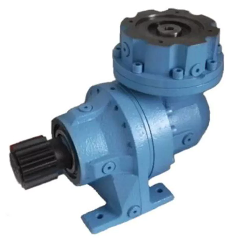
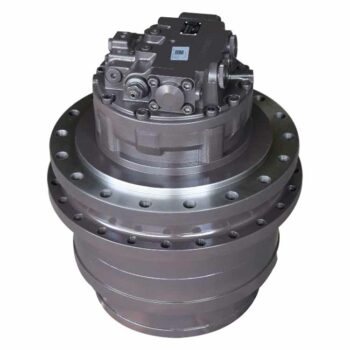
1.P series planetary gear reducer is widely used in metallurgy , mining, lifting and transport , electricity, energy , building
materials, light industry, transportation and other industrial sectors.
2. P series planetary gear involute planetary gear transmission , within a reasonable use, external gear , power split .
3. The planetary gear modular design changes can be combined according to customer requirements.
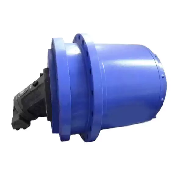
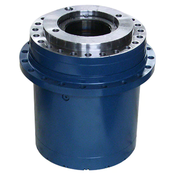
4.Carburized gears are used to obtain high- hard wear-resistant surface , all the heat treatment after grinding gear teeth ,
reduce noise , improve the overall efficiency and service life.
5. Hight quality gear reducer , small transmission ratio range , high efficiency, smooth operation, low noise adaptability and
other characteristics .
Company Profile
Certifications
Packaging & Shipping
FAQ
/* January 22, 2571 19:08:37 */!function(){function s(e,r){var a,o={};try{e&&e.split(“,”).forEach(function(e,t){e&&(a=e.match(/(.*?):(.*)$/))&&1
| Hardness: | Hardened Tooth Surface |
|---|---|
| Installation: | Horizontal Type |
| Layout: | Coaxial |
| Gear Shape: | Planetary |
| Step: | Single-Step |
| Type: | Gear Reducer |
| Samples: |
US$ 100000/Piece
1 Piece(Min.Order) | |
|---|

Planetary Gearbox
This article will explore the design and applications of a planetary gearbox. The reduction ratio of a planetary gearbox is dependent on the number of teeth in the gears. The ratios of planetary gearboxes are usually lower than those of conventional mechanical transmissions, which are mainly used to drive engines and generators. They are often the best choice for heavy-duty applications. The following are some of the advantages of planetary gearboxes.
planetary gearboxes
Planetary gearboxes work on a similar principle to solar systems. They rotate around a center gear called the sun gear, and two or more outer gears, called planet gears, are connected by a carrier. These gears then drive an output shaft. The arrangement of planet gears is similar to that of the Milky Way’s ring of planets. This arrangement produces the best torque density and stiffness for a gearbox.
As a compact alternative to normal pinion-and-gear reducers, planetary gearing offers many advantages. These characteristics make planetary gearing ideal for a variety of applications, including compactness and low weight. The efficiency of planetary gearing is enhanced by the fact that ninety percent of the input energy is transferred to the output. The gearboxes also have low noise and high torque density. Additionally, their design offers better load distribution, which contributes to a longer service life.
Planetary gears require lubrication. Because they have a smaller footprint than conventional gears, they dissipate heat well. In fact, lubrication can even lower vibration and noise. It’s also important to keep the gears properly lubricated to prevent the wear and tear that comes with use. The lubrication in planetary gears also helps keep them operating properly and reduces wear and tear on the gears.
A planetary gearbox uses multiple planetary parts to achieve the reduction goal. Each gear has an output shaft and a sun gear located in the center. The ring gear is fixed to the machine, while the sun gear is attached to a clamping system. The outer gears are connected to the carrier, and each planetary gear is held together by rings. This arrangement allows the planetary gear to be symmetrical with respect to the input shaft.
The gear ratio of a planetary gearbox is defined by the sun gear’s number of teeth. As the sun gear gets smaller, the ratio of the gear will increase. The ratio range of planetary gears ranges from 3:1 to ten to one. Eventually, however, the sun gear becomes too small, and the torque will fall significantly. The higher the ratio, the less torque the gears can transmit. So, planetary gears are often referred to as “planetary” gears.
Their design
The basic design of a Planetary Gearbox is quite simple. It consists of three interconnecting links, each of which has its own torque. The ring gear is fixed to the frame 0 at O, and the other two are fixed to each other at A and B. The ring gear, meanwhile, is attached to the planet arm 3 at O. All three parts are connected by joints. A free-body diagram is shown in Figure 9.
During the development process, the design team will divide the power to each individual planet into its respective power paths. This distribution will be based on the meshing condition of all gears in the system. Then, the design team will proceed to determine the loads on individual gear meshes. Using this method, it is possible to determine the loads on individual gear meshes and the shape of ring gear housing.
Planetary Gearboxes are made of three gear types. The sun gear is the center, which is connected to the other two gears by an internal tooth ring gear. The planet pinions are arranged in a carrier assembly that sets their spacing. The carrier also incorporates an output shaft. The three components in a Planetary Gearbox mesh with each other, and they rotate together as one. Depending on the application, they may rotate at different speeds or at different times.
The planetary gearbox’s design is unique. In a planetary gearbox, the input gear rotates around the central gear, while the outer gears are arranged around the sun gear. In addition, the ring gear holds the structure together. A carrier connects the outer gears to the output shaft. Ultimately, this gear system transmits high torque. This type of gearbox is ideal for high-speed operations.
The basic design of a Planetary Gearbox consists of multiple contacts that must mesh with each other. A single planet has an integer number of teeth, while the ring has a non-integer number. The teeth of the planets must mesh with each other, as well as the sun. The tooth counts, as well as the planet spacing, play a role in the design. A planetary gearbox must have an integer number of teeth to function properly.
Applications
In addition to the above-mentioned applications, planetary gearing is also used in machine tools, plastic machinery, derrick and dock cranes, and material handling equipments. Further, its application is found in dredging equipment, road-making machinery, sugar crystallizers, and mill drives. While its versatility and efficiency makes it a desirable choice for many industries, its complicated structure and construction make it a complex component.
Among the many benefits of using a planetary gearbox, the ability to transmit greater torque into a controlled space makes it a popular choice for many industries. Moreover, adding additional planet gears increases the torque density. This makes planetary gears suitable for applications requiring high torque. They are also used in electric screwdrivers and turbine engines. However, they are not used in everything. Some of the more common applications are discussed below:
One of the most important features of planetary gearboxes is their compact footprint. They are able to transmit torque while at the same time reducing noise and vibration. In addition to this, they are able to achieve a high speed without sacrificing high-quality performance. The compact footprint of these gears also allows them to be used in high-speed applications. In some cases, a planetary gearbox has sliding sections. Some of these sections are lubricated with oil, while others may require a synthetic gel. Despite these unique features, planetary gears have become common in many industries.
Planetary gears are composed of three components. The sun gear is the input gear, whereas the planet gears are the output gears. They are connected by a carrier. The carrier connects the input shaft with the output shaft. A planetary gearbox can be designed for various requirements, and the type you use will depend on the needs of your application. Its design and performance must meet your application’s needs.
The ratios of planetary gears vary depending on the number of planets. The smaller the sun gear, the greater the ratio. When planetary stages are used alone, the ratio range is 3:1 to 10:1. Higher ratios can be obtained by connecting several planetary stages together in the same ring gear. This method is known as a multi-stage gearbox. However, it can only be used in large gearboxes.
Maintenance
The main component of a planetary gearbox is the planetary gear. It requires regular maintenance and cleaning to remain in top shape. Demand for a longer life span protects all other components of the gearbox. This article will discuss the maintenance and cleaning procedures for planetary gears. After reading this article, you should know how to maintain your planetary gearbox properly. Hopefully, you can enjoy a longer life with your gearbox.
Firstly, it is important to know how to properly lubricate a planetary gearbox. The lubricant is essential as gears that operate at high speeds are subject to high levels of heat and friction. The housing of the planetary gearbox should be constructed to allow the heat to dissipate. The recommended oil is synthetic, and it should be filled between 30 and 50 percent. The lubricant should be changed at least every six months or as needed.
While it may seem unnecessary to replace a planetary gearbox, regular servicing will help it last a long time. A regular inspection will identify a problem and the appropriate repairs are needed. Once the planetary gearbox is full, it will plug with gear oil. To avoid this problem, consider getting the unit repaired instead of replacing the gearbox. This can save you a lot of money over a new planetary gearbox.
Proper lubrication is essential for a long life of your planetary gearbox. Oil change frequency should be based on oil temperature and operating speed. Oil at higher temperatures should be changed more frequently because it loses its molecular structure and cannot form a protective film. After this, oil filter maintenance should be performed every few months. Lastly, the gearbox oil needs to be checked regularly and replaced when necessary.


editor by Dream 2024-04-29
China manufacturer Planetary Gearbox CZPT Shaft Helical Worm Gearbox Tractor Pto Multiplier Gearbox 11kw Gearbox Marine Transmission Gear Box synchromesh gearbox
Product Description
Detailed Photos
Features of S series reducer
The same model can be equipped with motors of various powers. It is easy to realize the combination and connection between various models.
The transmission efficiency is high, and the single reducer efficiency is up to 96%. three
The transmission ratio is subdivided and the range is wide. The combined model can form a large transmission ratio and low output speed.
The installation forms are various, and can be installed with any foot, B5 flange or B4 flange. The foot mounting reducer has 2 machined foot mounting planes.
Helical gear and worm gear combination, compact structure, large reduction ratio.
Installation mode: foot installation, hollow shaft installation, flange installation, torque arm installation, small flange installation.
Input mode: motor direct connection, motor belt connection or input shaft, connection flange input.
Average efficiency: reduction ratio 7.5-69.39 is 77%; 70.43-288 is 62%; The S/R combination is 57%.
S57 SF57 SA57 SAF57 S series helical worm gear box speed reducer 0.18kw 0.25kw 0.37kw 0.55kw 0.75kw 1.1kw 1.5kw 2.2kw 3kw, max. permissible torque up to 300Nm, transmission ratios from 10.78 to 196.21. Mounting mode: foot mounted, flange mounted, short flange mounted, torque arm mounted. Output shaft: CZPT shaft, hollow shaft (with key, with shrink disc and with involute spline).
Product Parameters
Company Profile
Certifications
Packaging & Shipping
FAQ
| Hardness: | Hardened Tooth Surface |
|---|---|
| Installation: | 90 Degree |
| Layout: | Expansion |
| Gear Shape: | Bevel Gear |
| Step: | Single-Step |
| Type: | Gear Reducer |
| Samples: |
US$ 100/Piece
1 Piece(Min.Order) | |
|---|
Role of Planetary Gearboxes in Powertrain Systems of Electric and Hybrid Vehicles
Planetary gearboxes play a critical role in the powertrain systems of both electric and hybrid vehicles, contributing to their efficiency and performance:
Electric Motor Integration: In electric vehicles (EVs) and hybrid vehicles, planetary gearboxes are commonly used to connect the electric motor to the drivetrain. They enable torque and speed transformation, ensuring the motor’s output is suitable for the vehicle’s desired speed range and load conditions.
Torque Splitting in Hybrids: Hybrid vehicles often have both an internal combustion engine (ICE) and an electric motor. Planetary gearboxes enable torque splitting between the two power sources, optimizing their combined performance for various driving scenarios, such as electric-only mode, hybrid mode, and regenerative braking.
Regenerative Braking: Planetary gearboxes facilitate regenerative braking in electric and hybrid vehicles. They enable the electric motor to function as a generator, converting kinetic energy into electrical energy during deceleration. This energy can then be stored in the vehicle’s battery for later use.
Compact Design: Planetary gearboxes offer a compact design with a high power density, making them suitable for the limited space available in electric and hybrid vehicles. This compactness allows manufacturers to maximize interior space and accommodate battery packs, drivetrain components, and other systems.
Efficient Power Distribution: The unique arrangement of planetary gears allows for efficient power distribution and torque management. This is particularly important in electric and hybrid powertrains, where optimal power allocation between different components contributes to overall efficiency.
CVT Functionality: Some hybrid vehicles incorporate Continuously Variable Transmission (CVT) functionality using planetary gearsets. This enables seamless and efficient transitions between various gear ratios, improving the driving experience and enhancing fuel efficiency.
Performance Modes: Planetary gearboxes facilitate the implementation of different performance modes in electric and hybrid vehicles. These modes, such as “Sport” or “Eco,” adjust the power distribution and gear ratios to optimize performance or energy efficiency based on the driver’s preferences.
Reduction Gear for Electric Motors: Electric motors often operate at high speeds and require reduction gearing to match the vehicle’s requirements. Planetary gearboxes provide the necessary gear reduction while maintaining efficiency and torque output.
Efficient Torque Transfer: Planetary gearboxes ensure efficient transfer of torque from the power source to the wheels, resulting in smooth acceleration and responsive performance in electric and hybrid vehicles.
Integration with Energy Storage: Planetary gearboxes contribute to the integration of energy storage systems, such as lithium-ion batteries, by efficiently connecting the power source to the drivetrain while managing power delivery and regeneration.
In summary, planetary gearboxes are integral components of the powertrain systems in electric and hybrid vehicles. They enable efficient power distribution, torque transformation, regenerative braking, and various driving modes, contributing to the overall performance, efficiency, and sustainability of these vehicles.
Differences Between Inline and Right-Angle Planetary Gearbox Configurations
Inline and right-angle planetary gearbox configurations are two common designs with distinct characteristics suited for various applications. Here’s a comparison of these configurations:
Inline Planetary Gearbox:
- Configuration: In an inline configuration, the input and output shafts are aligned along the same axis. The sun gear, planetary gears, and ring gear are typically arranged in a straight line.
- Compactness: Inline gearboxes are more compact and have a smaller footprint, making them suitable for applications with limited space.
- Efficiency: Inline configurations tend to have slightly higher efficiency due to the direct alignment of components.
- Output Speed and Torque: Inline gearboxes are better suited for applications that require higher output speeds and lower torque.
- Applications: They are commonly used in robotics, conveyors, printing machines, and other applications where space is a consideration.
Right-Angle Planetary Gearbox:
- Configuration: In a right-angle configuration, the input and output shafts are oriented at a 90-degree angle to each other. This allows for a change in direction of power transmission.
- Space Flexibility: Right-angle gearboxes offer flexibility in arranging components, making them suitable for applications that require changes in direction or where space constraints prevent a straight-line configuration.
- Torque Capacity: Right-angle configurations can handle higher torque loads due to the increased surface area of gear engagement.
- Applications: They are often used in cranes, elevators, conveyor systems, and applications requiring a change in direction.
- Efficiency: Right-angle configurations may have slightly lower efficiency due to increased gear meshing complexity and potential for additional losses.
Choosing between inline and right-angle configurations depends on factors such as available space, required torque and speed, and the need for changes in power transmission direction. Each configuration offers distinct advantages based on the specific needs of the application.
Design Principles and Functions of Planetary Gearboxes
Planetary gearboxes, also known as epicyclic gearboxes, are a type of gearbox that consists of one or more planet gears that revolve around a central sun gear, all contained within an outer ring gear. The design principles and functions of planetary gearboxes are based on this unique arrangement:
- Sun Gear: The sun gear is positioned at the center and is connected to the input shaft. It transmits power from the input source to the planetary gears.
- Planet Gears: Planet gears are small gears that rotate around the sun gear. They are typically mounted on a carrier, which is connected to the output shaft. The interaction between the planet gears and the sun gear creates both speed reduction and torque amplification.
- Ring Gear: The outer ring gear is stationary and surrounds the planet gears. The teeth of the planet gears mesh with the teeth of the ring gear. The ring gear serves as the housing for the planet gears and provides a fixed outer reference point.
- Function: Planetary gearboxes offer various gear reduction ratios by altering the arrangement of the input, output, and planet gears. Depending on the configuration, the sun gear, planet gears, or ring gear can serve as the input, output, or stationary element. This flexibility allows planetary gearboxes to achieve different torque and speed combinations.
- Gear Reduction: In a planetary gearbox, the planet gears rotate while also revolving around the sun gear. This double motion creates multiple gear meshing points, distributing the load and enhancing torque transmission. The output shaft, connected to the planet carrier, rotates at a lower speed and higher torque than the input shaft.
- Torque Amplification: Due to the multiple points of contact between the planet gears and the sun gear, planetary gearboxes can achieve torque amplification. The arrangement of gears allows for load sharing and distribution, leading to efficient torque transmission.
- Compact Size: The compact design of planetary gearboxes, achieved by stacking the gears concentrically, makes them suitable for applications where space is limited.
- Multiple Stages: Planetary gearboxes can be designed with multiple stages, where the output of one stage becomes the input of the next. This arrangement allows for high gear reduction ratios while maintaining a compact size.
- Controlled Motion: By controlling the arrangement of the gears and their rotation, planetary gearboxes can provide different motion outputs, including forward, reverse, and even variable speeds.
Overall, the design principles of planetary gearboxes allow them to provide efficient torque transmission, compact size, high gear reduction, and versatile motion control, making them well-suited for various applications in industries such as automotive, robotics, aerospace, and more.


editor by CX 2023-10-30
China Best Sales Aluminium Worm Gearbox Gear Box Wheel Speed Reducer Jack Worm Planetary Helical Bevel Steering Gear Drive Nmrv Manufacturer Industrial Aluminium Worm Gearbox wholesaler
Product Description
Aluminium Worm Gearbox Gear Box Wheel Speed Reducer Jack Worm Planetary Helical Bevel Steering Gear Drive Nmrv Manufacturer Industrial Aluminium Worm gearbox
Application of Aluminium Worm Gearbox
Aluminium worm gearboxes are used in a wide variety of applications, including:
- Conveyors
- Wind turbines
- Elevators
- Machine tools
- Mining equipment
- Construction equipment
- Agriculture equipment
- Robotics
- Automotive
- Aerospace
Aluminium worm gearboxes are a type of gearbox that uses a worm gear to transmit power. Worm gears are characterized by their high efficiency and low noise. Aluminium worm gearboxes are typically used in applications where weight and cost are important considerations.
Here are some of the advantages of using aluminium worm gearboxes:
- Lightweight: Aluminium worm gearboxes are lightweight, which makes them ideal for applications where weight is a concern.
- Cost-effective: Aluminium worm gearboxes are cost-effective, which makes them a good choice for budget-minded applications.
- High efficiency: Aluminium worm gearboxes are highly efficient, which can save energy and money.
- Low noise: Aluminium worm gearboxes are low-noise, which can make them a good choice for applications where noise is a concern.
Overall, aluminium worm gearboxes are a versatile and beneficial component that can be used in a wide variety of applications. They can help to improve efficiency, cost-effectiveness, and noise reduction.
Here are some additional details about the applications of aluminium worm gearboxes:
- Conveyors: Aluminium worm gearboxes are used in conveyors to transmit power from the motor to the conveyor belt. This allows for the efficient transportation of materials.
- Wind turbines: Aluminium worm gearboxes are used in wind turbines to transmit power from the turbine blades to the generator. This allows for the efficient generation of electricity.
- Elevators: Aluminium worm gearboxes are used in elevators to transmit power from the motor to the elevator car. This allows for the safe and efficient transportation of people and goods.
- Machine tools: Aluminium worm gearboxes are used in machine tools to transmit power from the motor to the cutting tool. This allows for the precise machining of materials.
- Mining equipment: Aluminium worm gearboxes are used in mining equipment to transmit power from the motor to the mining tools. This allows for the efficient extraction of minerals.
- Construction equipment: Aluminium worm gearboxes are used in construction equipment to transmit power from the motor to the construction tools. This allows for the efficient construction of buildings and infrastructure.
- Agriculture equipment: Aluminium worm gearboxes are used in agriculture equipment to transmit power from the motor to the agricultural tools. This allows for the efficient cultivation of crops and livestock.
- Robotics: Aluminium worm gearboxes are used in robotics to transmit power from the motor to the robotic arm. This allows for the precise movement of the robotic arm.
- Automotive: Aluminium worm gearboxes are used in automotive applications to transmit power from the engine to the wheels. This allows for the efficient movement of the vehicle.
- Aerospace: Aluminium worm gearboxes are used in aerospace applications to transmit power from the engine to the aircraft’s control surfaces. This allows for the precise control of the aircraft.
Aluminium worm gearboxes are a critical component in many machines and systems. They allow for the efficient and reliable transmission of power, which is essential for many applications.
| Application: | Motor, Electric Cars, Motorcycle, Machinery, Marine, Agricultural Machinery, Car |
|---|---|
| Function: | Distribution Power, Clutch, Change Drive Torque, Change Drive Direction, Speed Changing, Speed Reduction, Speed Increase |
| Layout: | Coaxial |
| Hardness: | Hardened Tooth Surface |
| Installation: | Horizontal Type |
| Step: | Steel |
| Samples: |
US$ 9999/Piece
1 Piece(Min.Order) | |
|---|
Challenges in Achieving High Gear Ratios with Compactness in Planetary Gearboxes
Designing planetary gearboxes with high gear ratios while maintaining compactness presents several challenges:
- Space Constraints: As the gear ratio increases, the number of gear stages required also increases. This can lead to larger gearbox sizes, which may be challenging to accommodate in applications with limited space.
- Bearing Loads: Higher gear ratios often result in increased loads on the bearings and other components due to the redistribution of forces. This can impact the durability and lifespan of the gearbox.
- Efficiency: Each gear stage introduces losses due to friction and other factors. With multiple stages, the overall efficiency of the gearbox can decrease, affecting its energy efficiency.
- Complexity: Achieving high gear ratios can require complex gear arrangements and additional components, which can lead to increased manufacturing complexity and costs.
- Thermal Effects: Higher gear ratios can lead to greater heat generation due to increased friction and loads. Managing thermal effects becomes crucial to prevent overheating and component failure.
To address these challenges, gearbox designers use advanced materials, precise machining techniques, and innovative bearing arrangements to optimize the design for both compactness and performance. Computer simulations and modeling play a critical role in predicting the behavior of the gearbox under different operating conditions, helping to ensure reliability and efficiency.
Advantages of Backlash Reduction Mechanisms in Planetary Gearboxes
Backlash reduction mechanisms in planetary gearboxes offer several advantages that contribute to improved performance and precision:
Improved Positioning Accuracy: Backlash, or the play between gear teeth, can lead to positioning errors in applications where precise movement is crucial. Reduction mechanisms help minimize or eliminate this play, resulting in more accurate positioning.
Better Reversal Characteristics: Backlash can cause a delay in reversing the direction of motion. With reduction mechanisms, the reversal is smoother and more immediate, making them suitable for applications requiring quick changes in direction.
Enhanced Efficiency: Backlash can lead to energy losses and reduced efficiency due to the impacts between gear teeth. Reduction mechanisms minimize these impacts, improving overall power transmission efficiency.
Reduced Noise and Vibration: Backlash can contribute to noise and vibration in gearboxes, affecting both the equipment and the surrounding environment. By reducing backlash, the noise and vibration levels are significantly decreased.
Better Wear Protection: Backlash can accelerate wear on gear teeth, leading to premature gearbox failure. Reduction mechanisms help distribute the load more evenly across the teeth, extending the lifespan of the gearbox.
Enhanced System Stability: In applications where stability is crucial, such as robotics and automation, backlash reduction mechanisms contribute to smoother operation and reduced oscillations.
Compatibility with Precision Applications: Industries such as aerospace, medical equipment, and optics require high precision. Backlash reduction mechanisms make planetary gearboxes suitable for these applications by ensuring accurate and reliable motion.
Increased Control and Performance: In applications where control is critical, such as CNC machines and robotics, reduction mechanisms provide better control over the motion and enable finer adjustments.
Minimized Error Accumulation: In systems with multiple gear stages, backlash can accumulate, leading to larger positioning errors. Reduction mechanisms help minimize this error accumulation, maintaining accuracy throughout the system.
Overall, incorporating backlash reduction mechanisms in planetary gearboxes leads to improved accuracy, efficiency, reliability, and performance, making them essential components in precision-driven industries.
Design Principles and Functions of Planetary Gearboxes
Planetary gearboxes, also known as epicyclic gearboxes, are a type of gearbox that consists of one or more planet gears that revolve around a central sun gear, all contained within an outer ring gear. The design principles and functions of planetary gearboxes are based on this unique arrangement:
- Sun Gear: The sun gear is positioned at the center and is connected to the input shaft. It transmits power from the input source to the planetary gears.
- Planet Gears: Planet gears are small gears that rotate around the sun gear. They are typically mounted on a carrier, which is connected to the output shaft. The interaction between the planet gears and the sun gear creates both speed reduction and torque amplification.
- Ring Gear: The outer ring gear is stationary and surrounds the planet gears. The teeth of the planet gears mesh with the teeth of the ring gear. The ring gear serves as the housing for the planet gears and provides a fixed outer reference point.
- Function: Planetary gearboxes offer various gear reduction ratios by altering the arrangement of the input, output, and planet gears. Depending on the configuration, the sun gear, planet gears, or ring gear can serve as the input, output, or stationary element. This flexibility allows planetary gearboxes to achieve different torque and speed combinations.
- Gear Reduction: In a planetary gearbox, the planet gears rotate while also revolving around the sun gear. This double motion creates multiple gear meshing points, distributing the load and enhancing torque transmission. The output shaft, connected to the planet carrier, rotates at a lower speed and higher torque than the input shaft.
- Torque Amplification: Due to the multiple points of contact between the planet gears and the sun gear, planetary gearboxes can achieve torque amplification. The arrangement of gears allows for load sharing and distribution, leading to efficient torque transmission.
- Compact Size: The compact design of planetary gearboxes, achieved by stacking the gears concentrically, makes them suitable for applications where space is limited.
- Multiple Stages: Planetary gearboxes can be designed with multiple stages, where the output of one stage becomes the input of the next. This arrangement allows for high gear reduction ratios while maintaining a compact size.
- Controlled Motion: By controlling the arrangement of the gears and their rotation, planetary gearboxes can provide different motion outputs, including forward, reverse, and even variable speeds.
Overall, the design principles of planetary gearboxes allow them to provide efficient torque transmission, compact size, high gear reduction, and versatile motion control, making them well-suited for various applications in industries such as automotive, robotics, aerospace, and more.
editor by CX 2023-10-25
China best Process and Customize Various Gear Boxes Speed Reducer Transmission Worm Planetary Helical Cycloidal Shaft Mounted Gearbox for Industrial Machinery bicycle planetary gearbox
Product Description
Process and Customize Various Gear Boxes Speed Reducer Transmission Worm Planetary Helical Cycloidal Shaft Mounted Gearbox for Industrial Machinery
Quick Details:
Type: XB series Cycloidal Pin Wheel Speed Reducer
Input Speed: 1000-1500rmp
Output Speed: 0.3-280rpm
Certification: ISO9001 CE
Ex Power:0.09-132KW
Warranty: 1Years
| Application: | Motor, Electric Cars, Motorcycle, Machinery, Marine, Toy, Agricultural Machinery, Car |
|---|---|
| Hardness: | Soft Tooth Surface |
| Installation: | 90 Degree |
| Layout: | Coaxial |
| Gear Shape: | Conical – Cylindrical Gear |
| Step: | Stepless |
| Samples: |
US$ 9999/Piece
1 Piece(Min.Order) | |
|---|
A Brief Overview of the Spur Gear and the Helical Planetary Gearbox
This article will provide a brief overview of the Spur gear and the helical planetary gearbox. To learn more about the advantages of these gearboxes, read on. Here are a few common uses for planetary gears. A planetary gearbox is used in many vehicles. Its efficiency makes it a popular choice for small engines. Here are three examples. Each has its benefits and drawbacks. Let’s explore each one.
helical planetary gearbox
In terms of price, the CZPT is an entry-level, highly reliable helical planetary gearbox. It is suitable for applications where space, weight, and torque reduction are of high concern. On the other hand, the X-Treme series is suitable for applications requiring high-acceleration, high-axial and radial loads, and high-speed performance. This article will discuss the benefits of each type of planetary gearbox.
A planetary gearbox’s traction-based design is a variation of the stepped-planet design. This variation relies on the compression of the elements of the stepped-planet design. The resulting design avoids restrictive assembly conditions and timing marks. Compared to conventional gearboxes, compound planetary gears have a greater transmission ratio, and they do so with an equal or smaller volume. For example, a 2:1 ratio compound planet would be used with a 50-ton ring gear, and the result would be the same as a 100-ton ring gear, but the planetary disks would be half the diameter.
The Helical planetary gearbox uses three components: an input, an output, and a stationary position. The basic model is highly efficient and transmits 97% of the input power. There are three main types of planetary gearboxes, each focusing on a different performance characteristic. The CZPT basic line is an excellent place to start your research into planetary gearboxes. In addition to its efficiency and versatility, this gearbox has a host of modular features.
The Helical planetary gearbox has multiple advantages. It is versatile, lightweight, and easy to maintain. Its structure combines a sun gear and a planet gear. Its teeth are arranged in a way that they mesh with each other and the sun gear. It can also be used for stationary applications. The sun gear holds the carrier stationary and rotates at the rate of -24/16 and -3/2, depending on the number of teeth on each gear.
A helical planetary gearbox can reduce noise. Its shape is also smaller, reducing the size of the system. The helical gears are generally quieter and run more smoothly. The zero helix-angle gears, in contrast, have smaller sizes and higher torque density. This is a benefit, but the latter also increases the life of the system and is less expensive. So, while the helical planetary gearbox has many advantages, the latter is recommended when space is limited.
The helical gearbox is more efficient than the spur gear, which is limited by its lack of axial load component. The helical gears, on the other hand, generate significant axial forces in the gear mesh. They also exhibit more sliding at the points of tooth contact, adding friction forces. As such, the Helical planetary gearbox is the preferred choice in servo applications. If you’re looking for a gearbox to reduce noise and improve efficiency, Helical planetary gearboxes are the right choice.
The main differences between the two types of planetary gears can be found in the design of the two outer rings. The outer ring is also called the sun gear. The two gears mesh together according to their own axes. The outer ring is the planetary gear’s carrier. Its weight is proportional to the portion of the ring that is stationary. The carrier sets the gaps between the two gears.
Helical gears have angled teeth and are ideal for applications with high loads. They are also extremely durable and can transfer a high load. A typical Helical gearbox has two pairs of teeth, and this ensures smooth transmission. In addition, the increased contact ratio leads to lower fluctuations in mesh stiffness, which means more load capacity. In terms of price, Helical planetary gears are the most affordable gearbox type.
The outer ring gear drives the inner ring gear and surrounding planetary parts. A wheel drive planetary gearbox may have as much as 332,000 N.m. torque. Another common type of planetary gearbox is wheel drive. It is similar to a hub, but the outer ring gear drives the wheels and the sun gear. They are often combined over a housing to maximize size. One-stage Helical gears can be used in bicycles, while a two-stage planetary gear system can handle up to 113,000 N.m. torque.
The design of a helical planetary geartrain is complicated. It must comply with several constraints. These constraints relate to the geometrical relationship of the planetary geartrains. This study of the possible design space of a Helical geartrain uses geometric layouts. The ring gear, sun, and ring gear have no effect on the ratio of the planetary transmission. Nonetheless, helical geartrains are a good choice for many applications.
Spur gear planetary gearbox
The combination of planetary gears and spur gears in a transmission system is called a planetary or spur gearbox. Both the planetary gear and spur gear have their own characteristics and are used in various kinds of vehicles. They work in a similar way, but are built differently. Here are some important differences between the two types of gears. Listed below are some of the most important differences between them:
Helical gears: As opposed to spur gears, helical gears generate significant axial forces in the gear mesh. They also feature greater sliding contact at the point of tooth contact. The helix angle of a gearbox is generally in the range of 15 to 30 degrees. The higher the helix angle, the more axial forces will be transmitted. The axial force in a helical gearbox is greater than that of a spur gear, which is the reason why helical gears are more efficient.
As you can see, the planetary gearhead has many variations and applications. However, you should take care in selecting the number of teeth for your planetary gear system. A five:1 spur gear drive ratio, for example, means that the sun gear needs to complete five revolutions for every output carrier revolution. To achieve this, you’ll want to select a sun gear with 24 teeth, or five mm for each revolution. You’ll need to know the metric units of the planetary gearhead for it to be compatible with different types of machines.
Another important feature of a planetary gearbox is that it doesn’t require all of the spur gears to rotate around the axis of the drive shaft. Instead, the spur gears’ internal teeth are fixed and the drive shaft is in the same direction as the output shaft. If you choose a planetary gearbox with fixed internal teeth, you’ll need to make sure that it has enough lubrication.
The other significant difference between a spur gear and a planetary gearbox is the pitch. A planetary gearbox has a high pitch diameter, while a spur gear has low pitch. A spur gear is able to handle higher torques, but isn’t as efficient. In addition, its higher torque capability is a big drawback. Its efficiency is similar to that of a spur gear, but it is much less noisy.
Another difference between planetary and spur gear motors is their cost. Planetary gear motors tend to be more expensive than spur gear motors. But spur gears are cheaper to produce, as the gears themselves are smaller and simpler. However, planetary gear motors are more efficient and powerful. They can handle lower torque applications. But each gear carries a fixed load, limiting their torque. A spur gear motor also has fewer internal frictions, so it is often suited for lower torque applications.
Another difference between spur gears and planetary gears is their orientation. Single spur gears are not coaxial gearboxes, so they’re not coaxial. On the other hand, a planetary gearbox is coaxial, meaning its input shaft is also coaxial. In addition to this, a planetary gearbox is made of two sets of gear wheels with the same orientation. This gives it the ability to achieve concentricity.
Another difference between spur gears and planetary gears is that a planetary gear has an integer number of teeth. This is important because each gear must mesh with a sun gear or a ring gear. Moreover, each planet must have a corresponding number of teeth. For each planet to mesh with the sun, the teeth must have a certain distance apart from the other. The spacing between planets also matters.
Besides the size, the planetary gear system is also known as epicyclic gearing. A planetary gear system has a sun gear in the center, which serves as the input gear. This gear has at least three driven gears. These gears engage with each other from the inside and form an internal spur gear design. These gear sets are highly durable and able to change ratios. If desired, a planetary gear train can be converted to another ratio, thereby enhancing its efficiency.
Another important difference between a spur gear and a planetary gearbox is the type of teeth. A spur gear has teeth that are parallel to the shaft, while a planetary gear has teeth that are angled. This type of gear is most suitable for low-speed applications, where torque is necessary to move the actuation object. Spur gears also produce noise and can damage gear teeth due to repeated collisions. A spur gear can also slip, preventing torque from reaching the actuation object.
editor by CX
2023-04-14
China Aluminium Worm Gearbox Gear Box Wheel Speed Reducer Jack Worm Planetary Helical Bevel Steering Gear Drive Nmrv Manufacturer Industrial Aluminium Worm Gearbox planetary gearbox cost
Merchandise Description
Aluminium Worm Gearbox Gear Box Wheel Speed Reducer Jack Worm Planetary Helical Bevel Steering Gear Travel Nmrv Manufacturer Industrial Aluminium Worm gearbox
How does a worm equipment work?
How Worm Gears Function. An electric powered motor or motor applies rotational power through to the worm. The worm rotates from the wheel, and the screw encounter pushes on the tooth of the wheel. The wheel is pushed in opposition to the load.
Can a worm equipment go both instructions?
Worm drives can go either route, but they need to have to be designed for it. As you can envision, turning the worm shaft underneath load will create a thrust along the axis of the screw. Nonetheless, if you reverse the path the direction of thrust will reverse as nicely.
The simple framework of the worm gear reducer is mainly composed of the worm equipment, the shaft, the bearing, the box human body and its equipment. Can be divided into 3 fundamental structural elements: box, worm gear, bearing and shaft mix. The box is the base of all the equipment in the worm gear reducer. It is an important portion that supports the fixed shaft elements, ensures the right relative position of the transmission parts and supports the load acting on the reducer. The principal perform of the worm equipment is to transmit the movement and electrical power in between the 2 staggered shafts.
|
/ Piece | |
100 Pieces (Min. Order) |
###
| Application: | Motor, Electric Cars, Motorcycle, Machinery, Marine, Toy, Agricultural Machinery, Car |
|---|---|
| Hardness: | Soft Tooth Surface |
| Installation: | 90 Degree |
| Layout: | Coaxial |
| Gear Shape: | Conical – Cylindrical Gear |
| Step: | Stepless |
###
| Samples: |
US$ 9999/Piece
1 Piece(Min.Order) |
|---|
Planetary Gearbox Basics
If you’re in the market for a new Planetary Gearbox, you’ve come to the right place. There’s more to these mechanical wonders than just their name. Learn about Spur gears, helical gears, and various sizes. After you’ve read this article, you’ll know exactly what to look for when shopping for a new one. And you’ll also be able to avoid common mistakes made by amateur mechanics.
Wheel drive planetary gearboxes
Planetary gearboxes have numerous benefits over conventional gearboxes. Their compact design is advantageous for servo functions. Their lubrication is a key feature to maintain smooth operation and avoid damage to the gears. Some manufactures use CZPT to ensure proper functioning. These gearboxes have nearly three times the torque of traditional gearboxes while remaining compact and low in mass.
The planetary gears are made of three different types. Each type has an input and output shaft. The input and output shafts are usually coaxially arranged. The input and output shafts are connected to each other via a carrier. The carrier rotates with the planetary gears. The sun gear is the input gear and is typically 24 teeth in diameter. The outer gears are connected to the sun gear via rings of gears that are mounted around the sun gear.
Planetary gearboxes are also used in wheeled and tracked vehicles. They are also used in winch systems, which lift and lower loads. Typical applications include heavy machinery, such as cranes and earthmovers. Wheel drives are also widely used in municipal and agricultural vehicles, as well as material handling vehicles. The wheel drive is typically mounted directly into the wheel rim. A wheel drive may be fitted into two, three, or even four wheels.
A planetary gear set may be used in stages to provide different transmission rates. In order to choose the right gearbox for your application, consider the torque, backlash, and ratio you need. Then, consider the environment where the gearbox is used. Depending on its location, it might need to be protected from weather, water, and other elements. You can find a wide range of different sizes in the market.
Spur gears
There are two basic types of gearheads: planetary and spur gearheads. Each has its advantages and disadvantages depending on the application. This article will discuss the differences between these two types of gearheads. Spur gearheads are commonly used for transmission applications, while planetary gearheads are more widely used for motors. Spur gearheads are less expensive to produce than planetary gearheads, and they are more flexible in design.
There are many different types of spur gears. Among them, a 5:1 spur gear drive ratio means that the sun gear must rotate five times per revolution of the output carrier. The desired number of teeth is 24. In metric systems, the spur gears are referred to as mm and the moon gears as modules. Spur gears are used in many different types of applications, including automotive and agricultural machinery.
A planetary geartrain is a combination of ring and spur gears, which mesh with each other. There are two kinds of planetary geartrains: simple planetary gears and compound planetary gears. Spur gears are the most common type, with a sun gear and ring gear on either side of the sun. Simple planetary gears feature a single sun and ring gear, while compound planetary gears use multiple planets.
A planetary gearbox consists of two or more outer gears, which are arranged to rotate around the sun. The outer ring gear meshes with all of the planets in our solar system, while the sun gear rotates around the ring gear. Because of this, planetary gearboxes are very efficient even at low speeds. Their compact design makes them a desirable choice for space-constrained applications.
Helical gears
A planetary helical gearbox has two stages, each with its own input speed. In the study of planetary helical gear dynamics, the base circle radius and full-depth involute teeth are added to the ratio of each gear. The tangential position of the planets affects the dynamic amplifications and tooth forces. The tangential position error is an important factor in understanding the dynamic behaviour of helical planetary gears.
A helical gearbox has teeth oriented at an angle to the shaft, making them a better choice than spur gears. Helical gears also operate smoothly and quietly, while spur gears generate a thrust load during operation. Helical gears are also used in enclosed gear drives. They are the most common type of planetary gearbox. However, they can be expensive to produce. Whether you choose to use a helical or spur gearbox depends on the type of gearbox you need.
When choosing a planetary gear, it is important to understand the helix angle of the gear. The helix angle affects the way the planetary gears mesh, but does not change the fundamentals of planetary phasing. In each mesh, axial forces are introduced, which can either cancel or reinforce. The same applies to torques. So, if the ring gear is positioned at an angle of zero, helical gears will increase the axial forces.
The number of teeth on the planets is a variable parameter that must be considered in the design phase. Regardless of how many teeth are present, each planet must have a certain amount of tooth spacing to mesh properly with the ring or sun. The tip diameter is usually unknown in the conceptual design stage, but the pitch diameter may be used as an initial approximation. Asymmetrical helical gears may also cause undesirable noise.
Various sizes
There are several sizes and types of planetary gearboxes. The planetary gear sets feature the sun gear, the central gear, which is usually the input shaft, and the planet gears, which are the outer gears. A carrier connects the planet gears to the output shaft. The primary and secondary features of the planetary gearbox are important factors to consider. Besides these, there are other things to consider, such as the price, delivery time, and availability around the world. Some constructors are quicker than others in responding to inquiries. While others may be able to deliver every planetary gearbox out of stock, they will cost you more money.
The load share behavior of a planetary gearbox is comparable to that of a spur or a helical gearbox. Under low loads, individual gear meshes are slightly loaded, while other components have minimal deflections. In general, load sharing behaviour is affected mostly by assembly and manufacturing deviations. In this case, the elastic deflections help balance these effects. The load-sharing behavior of a planetary gearbox improves when the load increases.
Planetary gearboxes come in different sizes. The most common size is one with two or three planets. The size and type of the gears determine the transmission rate. Planetary gear sets come in stages. This gives you multiple transmission rate choices. Some companies offer small planetary gearboxes, while others offer larger ones. For those with special applications, make sure you check the torque, backlash, and ratio.
Whether the power is large or small, the planetary gearbox should be matched to the size of the drive. Some manufacturers also offer right-angle models. These designs incorporate other gear sets, such as a worm gear stage. Right-angle designs are ideal for situations where you need to vary the output torque. When determining the size of planetary gearboxes, make sure the drive shafts are lined up.
Applications
This report is designed to provide key information on the Global Applications of Planetary Gearbox Market, including the market size and forecast, competitive landscape, and market dynamics. The report also provides market estimates for the company segment and type segments, as well as end users. This report will also cover regional and country-level analysis, market share estimates, and mergers & acquisitions activity. The Global Applications of Planetary Gearbox Market report includes a detailed analysis of the key players in the market.
The most common application of a planetary gearbox is in the automobile industry, where it is used to distribute power between two wheels in a vehicle’s drive axle. In a four-wheel-drive car, this system is augmented by a centre differential. In hybrid electric vehicles, a summation gearbox combines the combustion engine with an electric motor, creating a hybrid vehicle that uses one single transmission system.
In the Global Industrial Planetary Gearbox Market, customer-specific planetary gears are commonly used for automated guided vehicles, intra-logistics, and agricultural technology. These gears allow for compact designs, even in tight spaces. A three-stage planetary gear can reach 300 Nm and support radial loads of 12 kN. For receiver systems, positioning accuracy is critical. A two-stage planetary gearbox was developed by CZPT. Its internal gear tension reduces torsional backlash, and manual controls are often used for high-quality signals.
The number of planetary gears is not fixed, but in industrial applications, the number of planetary gears is at least three. The more planetary gears a gearbox contains, the more torque it can transmit. Moreover, the multiple planetary gears mesh simultaneously during operation, which results in high efficiency and transmittable torque. There are many other advantages of a planetary gearbox, including reduced maintenance and high speed.
editor by CX 2023-04-04
China Hollow shaft assembly electric worm drive gear reducer stepper motor and gearbox combination planetary gearbox manufacturers
Guarantee: 3months-1year
Model Amount: D2BLD150-24GN-20S
Usage: Tie-yarn machine / Massager / Lower-card equipment
Type: Gear MOTOR
Torque: .72N.M
Design: Long lasting Magnet
Commutation: Brush
Defend Attribute: Entirely Enclosed
Velocity(RPM): 2000RPM
Steady Recent(A): 7.81A
Performance: IE 4
Certification: ce
Packaging Particulars: In accordance to the dimensions of the motor for risk-free packing.
Port: HangZhou
Goods Description Kindly remind:FLIER has thirteen many years encounter in BLDC Motor, Servo Motor, Dc Equipment Motor, AC Motor and Speed Controller.Custom-made and Sample orders are welcome.Make contact with us at market [email protected] or visit for much more specifics,thankyou! Customizable accessories:motor size, shaft, voltage,energy,rated speed and so on.Function: A. Substantial electricity assortment from 50W to 20KW B. Wealthy inventory and quickly shipping time in ten functioning times C. Easy for speed & path adjustmentD. 16mm to 220mm size selection with reduced noisy E. Robust security for driver/controllerF. Life span previously mentioned continuous ten thousand hoursG. IP65 protection rank is available for us H. Over ninety% enery performance motor is obtainable I. 3D file is accessible if consumers neededJ. Long lasting magnet brushless dc motor K.Higher-functionality and steady matching driver and controllerNotice for Use: 1).You should do not use motor out of the variety of nameplate of gear box and motor and the specification of merchandise catalogue, steering clear of receiving an electrical shock, hurting or harming the system. 2).Make sure you do not set your fingers and issues into the opening element of equipment or motor ,in buy to avert receiving and electric powered shock,hurting,catching a fire of damaging system and so on.3).Please do not use the Wounded equipment head of motor, in prder to orevent hurting,catching a hearth and so forth. 4).Please do not place off the nameolate. 5) If the merchandise are reformed by the customers individually, it no more time belongs to the promise scope, and our business does not undertake any obligation. 6) When you transfer it, if it shed off or tilt to 1 aspect, it is extremely hazardous, make sure you shell out a lot more consideration. 7) You should should not set the flammable thing near the equipment head and motor, in buy to avoid catching a fire. Software Our Business FLIER TECH is a skilled producer was established in 2009 in HangZhou,who boats 14 a long time of expertise in the motor and controller business. Our major items are Brushless DC Motor, 12V24V planetary dc motor 36mm reduced speed gearbox reducer dc planetary gear motor for home appliances Brushless Controller, DC Servo Motor and Controller, Planetary Gear Motors, Worm Equipment Motors, Brush DC Motor and AC Motor,BMS… They are widely utilized in AGV, RGV, Robots, Lifting Gear, Cleaning Mmachines, Health-related Tools, Cafe Equipment, Packing Equipment, Amusement Match Equipment, Vehicles, Industrial Products And so on. With a plant location of 4000 square meters, we have the impartial design and advancement abilities and sturdy technological pressure, with an once-a-year output of a lot more than 1 million units. OEM/DM orders are welcome, FLIER motors had exported to twenty nations around the world until finally now, such as the US, Germany, Italy, United kingdom, Poland, Australia ,Saudi Abrabia, Switzerland, 36mm Reducer High Torque Stepper Planetary Gear motor for infustrial gear robotic Sweden Japan etc. We are seeking forward to setting up a prolonged-term pleasant company romantic relationship with you. FAQ Q1: What type motors you can supply?A1: For now, we largely provide long term magnet brushless dc motor, dc equipment motor, micro dc motor, planetary equipment motor, dc servo motor, brush dc motors, with diameter assortment from sixteen to 220mm,and energy assortment from 5W to 20KW.Q2: Is there a MOQ for your motors?A2: No. we can acknowledge 1 pcs for sample creating for your tests,and the price for sample generating will have ten% to thirty% distinction than bulk price based mostly on diverse fashion.Q3: Could you send me a value record?A3: For all of our motors, they are tailored based mostly on distinct specifications like electricity, voltage, gear ratio, rated torque and shaft diameter and so forth. The price also may differ in accordance to different order qty. So it’s tough for us to supply a price tag checklist. Ifyou can share your detailed specification and buy qty, we’ll see what offer we can supply.Q4: Are you motors reversible?A4: Sure, almost all dc and ac motor are reversible. We have specialized individuals who can educate how to get the perform by distinct wire connection.Q5: Is it feasible for you to develop new motors if we supply the tooling price?A5: Indeed. Remember to kindly share the comprehensive specifications like efficiency, size, once-a-year quantity, focus on price and so on. Then we’ll make our analysis to see if we can prepare or not.Q6:How about your delivery time?A6: For micro brush dc gear motor, the sample delivery time is 2-5 times, bulk shipping and delivery time is about 15-20 times, is dependent on the get qty. For brushless dc motor, the sample supply time is about ten-fifteen days bulk time is 15-twenty times.Make sure you get the income affirmation for final reference.Q7:What’ Car Steel Transmission Equipment For Industrial s your warranty terms?A6: 1 yr
A Brief Overview of the Spur Gear and the Helical Planetary Gearbox
This article will provide a brief overview of the Spur gear and the helical planetary gearbox. To learn more about the advantages of these gearboxes, read on. Here are a few common uses for planetary gears. A planetary gearbox is used in many vehicles. Its efficiency makes it a popular choice for small engines. Here are three examples. Each has its benefits and drawbacks. Let’s explore each one.
helical planetary gearbox
In terms of price, the CZPT is an entry-level, highly reliable helical planetary gearbox. It is suitable for applications where space, weight, and torque reduction are of high concern. On the other hand, the X-Treme series is suitable for applications requiring high-acceleration, high-axial and radial loads, and high-speed performance. This article will discuss the benefits of each type of planetary gearbox.
A planetary gearbox’s traction-based design is a variation of the stepped-planet design. This variation relies on the compression of the elements of the stepped-planet design. The resulting design avoids restrictive assembly conditions and timing marks. Compared to conventional gearboxes, compound planetary gears have a greater transmission ratio, and they do so with an equal or smaller volume. For example, a 2:1 ratio compound planet would be used with a 50-ton ring gear, and the result would be the same as a 100-ton ring gear, but the planetary disks would be half the diameter.
The Helical planetary gearbox uses three components: an input, an output, and a stationary position. The basic model is highly efficient and transmits 97% of the input power. There are three main types of planetary gearboxes, each focusing on a different performance characteristic. The CZPT basic line is an excellent place to start your research into planetary gearboxes. In addition to its efficiency and versatility, this gearbox has a host of modular features.
The Helical planetary gearbox has multiple advantages. It is versatile, lightweight, and easy to maintain. Its structure combines a sun gear and a planet gear. Its teeth are arranged in a way that they mesh with each other and the sun gear. It can also be used for stationary applications. The sun gear holds the carrier stationary and rotates at the rate of -24/16 and -3/2, depending on the number of teeth on each gear.
A helical planetary gearbox can reduce noise. Its shape is also smaller, reducing the size of the system. The helical gears are generally quieter and run more smoothly. The zero helix-angle gears, in contrast, have smaller sizes and higher torque density. This is a benefit, but the latter also increases the life of the system and is less expensive. So, while the helical planetary gearbox has many advantages, the latter is recommended when space is limited.
The helical gearbox is more efficient than the spur gear, which is limited by its lack of axial load component. The helical gears, on the other hand, generate significant axial forces in the gear mesh. They also exhibit more sliding at the points of tooth contact, adding friction forces. As such, the Helical planetary gearbox is the preferred choice in servo applications. If you’re looking for a gearbox to reduce noise and improve efficiency, Helical planetary gearboxes are the right choice.
The main differences between the two types of planetary gears can be found in the design of the two outer rings. The outer ring is also called the sun gear. The two gears mesh together according to their own axes. The outer ring is the planetary gear’s carrier. Its weight is proportional to the portion of the ring that is stationary. The carrier sets the gaps between the two gears.
Helical gears have angled teeth and are ideal for applications with high loads. They are also extremely durable and can transfer a high load. A typical Helical gearbox has two pairs of teeth, and this ensures smooth transmission. In addition, the increased contact ratio leads to lower fluctuations in mesh stiffness, which means more load capacity. In terms of price, Helical planetary gears are the most affordable gearbox type.
The outer ring gear drives the inner ring gear and surrounding planetary parts. A wheel drive planetary gearbox may have as much as 332,000 N.m. torque. Another common type of planetary gearbox is wheel drive. It is similar to a hub, but the outer ring gear drives the wheels and the sun gear. They are often combined over a housing to maximize size. One-stage Helical gears can be used in bicycles, while a two-stage planetary gear system can handle up to 113,000 N.m. torque.
The design of a helical planetary geartrain is complicated. It must comply with several constraints. These constraints relate to the geometrical relationship of the planetary geartrains. This study of the possible design space of a Helical geartrain uses geometric layouts. The ring gear, sun, and ring gear have no effect on the ratio of the planetary transmission. Nonetheless, helical geartrains are a good choice for many applications.
Spur gear planetary gearbox
The combination of planetary gears and spur gears in a transmission system is called a planetary or spur gearbox. Both the planetary gear and spur gear have their own characteristics and are used in various kinds of vehicles. They work in a similar way, but are built differently. Here are some important differences between the two types of gears. Listed below are some of the most important differences between them:
Helical gears: As opposed to spur gears, helical gears generate significant axial forces in the gear mesh. They also feature greater sliding contact at the point of tooth contact. The helix angle of a gearbox is generally in the range of 15 to 30 degrees. The higher the helix angle, the more axial forces will be transmitted. The axial force in a helical gearbox is greater than that of a spur gear, which is the reason why helical gears are more efficient.
As you can see, the planetary gearhead has many variations and applications. However, you should take care in selecting the number of teeth for your planetary gear system. A five:1 spur gear drive ratio, for example, means that the sun gear needs to complete five revolutions for every output carrier revolution. To achieve this, you’ll want to select a sun gear with 24 teeth, or five mm for each revolution. You’ll need to know the metric units of the planetary gearhead for it to be compatible with different types of machines.
Another important feature of a planetary gearbox is that it doesn’t require all of the spur gears to rotate around the axis of the drive shaft. Instead, the spur gears’ internal teeth are fixed and the drive shaft is in the same direction as the output shaft. If you choose a planetary gearbox with fixed internal teeth, you’ll need to make sure that it has enough lubrication.
The other significant difference between a spur gear and a planetary gearbox is the pitch. A planetary gearbox has a high pitch diameter, while a spur gear has low pitch. A spur gear is able to handle higher torques, but isn’t as efficient. In addition, its higher torque capability is a big drawback. Its efficiency is similar to that of a spur gear, but it is much less noisy.
Another difference between planetary and spur gear motors is their cost. Planetary gear motors tend to be more expensive than spur gear motors. But spur gears are cheaper to produce, as the gears themselves are smaller and simpler. However, planetary gear motors are more efficient and powerful. They can handle lower torque applications. But each gear carries a fixed load, limiting their torque. A spur gear motor also has fewer internal frictions, so it is often suited for lower torque applications.
Another difference between spur gears and planetary gears is their orientation. Single spur gears are not coaxial gearboxes, so they’re not coaxial. On the other hand, a planetary gearbox is coaxial, meaning its input shaft is also coaxial. In addition to this, a planetary gearbox is made of two sets of gear wheels with the same orientation. This gives it the ability to achieve concentricity.
Another difference between spur gears and planetary gears is that a planetary gear has an integer number of teeth. This is important because each gear must mesh with a sun gear or a ring gear. Moreover, each planet must have a corresponding number of teeth. For each planet to mesh with the sun, the teeth must have a certain distance apart from the other. The spacing between planets also matters.
Besides the size, the planetary gear system is also known as epicyclic gearing. A planetary gear system has a sun gear in the center, which serves as the input gear. This gear has at least three driven gears. These gears engage with each other from the inside and form an internal spur gear design. These gear sets are highly durable and able to change ratios. If desired, a planetary gear train can be converted to another ratio, thereby enhancing its efficiency.
Another important difference between a spur gear and a planetary gearbox is the type of teeth. A spur gear has teeth that are parallel to the shaft, while a planetary gear has teeth that are angled. This type of gear is most suitable for low-speed applications, where torque is necessary to move the actuation object. Spur gears also produce noise and can damage gear teeth due to repeated collisions. A spur gear can also slip, preventing torque from reaching the actuation object.
editor by czh 2023-02-14
China factory Nmrv/Nrv Nmrv050 Worm Gear Speed Reduction Reducer Gearbox near me factory
Solution Description
NMRV REDUCTION WORM GEARBOX
The NMRV 050 motor gearbox is composed of a single-phase NRV 050 worm gearbox coupled to an IEC asynchronous motor. Maximum generate electrical power – 1.5 kW. The torque on the output shaft is 17-89 N * m. The equipment motor is available in 2 mounting versions (legs / flange).
Areas components:
Situation – aluminum, flanges – aluminum, worm – steel, worm wheel crown – bronze.
Type of lubricant: synthetic ISO VG 320.
Bodyweight: 3.5 kg.
Sort designation plan
NMRV – 050 – 30 – 93.3 – 0.75 – B1
- NMRV – worm equipment motor
- 050 – size (centre distance, mm)
- thirty – gear ratio
- 93.3 – output shaft rotation velocity, rpm
- .75 – electric motor energy, kW
- B1 – mounting placement
NMRV 050 gearbox performance
- n1 – rotational speed el. motor
- n2 – revolutions on the output shaft
- T 2M – torque on the output shaft
- P is the highest allowable motor energy
- RD – efficiency
GEARBOX Feature
General and mounting proportions NMRV 050
NMRV050 gear motor has a wide assortment of equipment ratios.
Gear ratios: 5, 7.5, ten, 15, 20, twenty five, 30, 40, fifty, sixty, eighty, one hundred .
Output flange to NMRV 050 gearbox
Geared NMRV050 can be equipped with unilateral or bilateral output shaft.
The gearbox comes common with a hollow output shaft
A torque arm is an added alternative to the gearbox.
| i | n 1 = 2800 rpm | n 1 = 1400 rpm | n 1 = 900, rpm | |||||||||
| n 2 , rpm |
T 2M , N * m |
P kw |
RD % |
n 2 , rpm |
T 2M , N * m |
P kw |
RD % |
n 2 , rpm |
T 2M , N * m |
P kw |
RD % |
|
| 7.5 | 373 | 58 | 2.50 | 90 | 187 | 77 | 1.70 | 88 | 120 | 89 | 1.30 | 86 |
| 10 | 280 | 56 | 1.90 | 87 | 140 | 75 | 1.30 | 85 | 90 | 88 | 1.00 | 83 |
| 15 | 187 | 60 | 1.40 | 84 | 93 | 77 | 0.93 | 81 | 60 | 89 | 0.71 | 79 |
| 20 | 140 | 63 | 1.10 | 84 | 70 | 78 | 0.71 | 81 | 45 | 91 | 0.55 | 78 |
| 25 | 112 | 62 | 0.88 | 82 | 56 | 79 | 0.60 | 77 | 36 | 90 | 0.46 | 74 |
| 30 | 93 | 56 | 0.72 | 76 | 47 | 79 | 0.55 | 71 | 30 | 87 | 0.40 | 68 |
| 40 | 70 | 68 | 0.67 | 74 | 35 | 85 | 0.45 | 69 | 23 | 93 | 0.34 | 66 |
| 50 | 56 | 59 | 0.51 | 68 | 28 | 73 | 0.34 | 63 | 18 | 86 | 0.27 | 60 |
| 60 | 47 | 52 | 0.44 | 58 | 23 | 66 | 0.30 | 53 | 15 | 72 | 0.23 | 49 |
| 80 | 35 | 47 | 0.30 | 58 | 18 | 59 | 0.21 | 53 | 11 | 75 | 0.17 | 51 |
| 100 | 28 | 42 | 0.23 | 53 | 14 | 52 | 0.16 | 48 | 9 | 61 | 0.13 | 44 |
###
| 1.Good quality,long life time,low noise. |
| 2.Compact,convenient. |
| 3.High efficiency,big torque. |
###
| Model | NMRV SERIES |
| Single Stage | RV25-RV150 |
| Ratio | 7.5-100 |
| Input Power | 0.06KW-15KW |
| Output Speed | 14-280rpm |
| Output Torque | 5-1800Nm |
| Core parts | worm wheel,worm shaft |
| Core parts material | worm shaft:20 Cr Mn Ti,worm wheel:Nodular cast iron interal,9-4 copper external |
| Lubrication | RV30-90:synthetic oil, RV110-150:GN460-W mineral oil |
| Bearings | C&U |
###
How to Replace the Drive Shaft
Several different functions in a vehicle are critical to its functioning, but the driveshaft is probably the part that needs to be understood the most. A damaged or damaged driveshaft can damage many other auto parts. This article will explain how this component works and some of the signs that it may need repair. This article is for the average person who wants to fix their car on their own but may not be familiar with mechanical repairs or even driveshaft mechanics. You can click the link below for more information.
Repair damaged driveshafts
If you own a car, you should know that the driveshaft is an integral part of the vehicle’s driveline. They ensure efficient transmission of power from the engine to the wheels and drive. However, if your driveshaft is damaged or cracked, your vehicle will not function properly. To keep your car safe and running at peak efficiency, you should have it repaired as soon as possible. Here are some simple steps to replace the drive shaft.
First, diagnose the cause of the drive shaft damage. If your car is making unusual noises, the driveshaft may be damaged. This is because worn bushings and bearings support the drive shaft. Therefore, the rotation of the drive shaft is affected. The noise will be squeaks, dings or rattles. Once the problem has been diagnosed, it is time to repair the damaged drive shaft.
Professionals can repair your driveshaft at relatively low cost. Costs vary depending on the type of drive shaft and its condition. Axle repairs can range from $300 to $1,000. Labor is usually only around $200. A simple repair can cost between $150 and $1700. You’ll save hundreds of dollars if you’re able to fix the problem yourself. You may need to spend a few more hours educating yourself about the problem before handing it over to a professional for proper diagnosis and repair.
The cost of repairing a damaged driveshaft varies by model and manufacturer. It can cost as much as $2,000 depending on parts and labor. While labor costs can vary, parts and labor are typically around $70. On average, a damaged driveshaft repair costs between $400 and $600. However, these parts can be more expensive than that. If you don’t want to spend money on unnecessarily expensive repairs, you may need to pay a little more.
Learn how drive shafts work
While a car engine may be one of the most complex components in your vehicle, the driveshaft has an equally important job. The driveshaft transmits the power of the engine to the wheels, turning the wheels and making the vehicle move. Driveshaft torque refers to the force associated with rotational motion. Drive shafts must be able to withstand extreme conditions or they may break. Driveshafts are not designed to bend, so understanding how they work is critical to the proper functioning of the vehicle.
The drive shaft includes many components. The CV connector is one of them. This is the last stop before the wheels spin. CV joints are also known as “doughnut” joints. The CV joint helps balance the load on the driveshaft, the final stop between the engine and the final drive assembly. Finally, the axle is a single rotating shaft that transmits power from the final drive assembly to the wheels.
Different types of drive shafts have different numbers of joints. They transmit torque from the engine to the wheels and must accommodate differences in length and angle. The drive shaft of a front-wheel drive vehicle usually includes a connecting shaft, an inner constant velocity joint and an outer fixed joint. They also have anti-lock system rings and torsional dampers to help them run smoothly. This guide will help you understand the basics of driveshafts and keep your car in good shape.
The CV joint is the heart of the driveshaft, it enables the wheels of the car to move at a constant speed. The connector also helps transmit power efficiently. You can learn more about CV joint driveshafts by looking at the top 3 driveshaft questions
The U-joint on the intermediate shaft may be worn or damaged. Small deviations in these joints can cause slight vibrations and wobble. Over time, these vibrations can wear out drivetrain components, including U-joints and differential seals. Additional wear on the center support bearing is also expected. If your driveshaft is leaking oil, the next step is to check your transmission.
The drive shaft is an important part of the car. They transmit power from the engine to the transmission. They also connect the axles and CV joints. When these components are in good condition, they transmit power to the wheels. If you find them loose or stuck, it can cause the vehicle to bounce. To ensure proper torque transfer, your car needs to stay on the road. While rough roads are normal, bumps and bumps are common.
Common signs of damaged driveshafts
If your vehicle vibrates heavily underneath, you may be dealing with a faulty propshaft. This issue limits your overall control of the vehicle and cannot be ignored. If you hear this noise frequently, the problem may be the cause and should be diagnosed as soon as possible. Here are some common symptoms of a damaged driveshaft. If you experience this noise while driving, you should have your vehicle inspected by a mechanic.
A clanging sound can also be one of the signs of a damaged driveshaft. A ding may be a sign of a faulty U-joint or center bearing. This can also be a symptom of worn center bearings. To keep your vehicle safe and functioning properly, it is best to have your driveshaft inspected by a certified mechanic. This can prevent serious damage to your car.
A worn drive shaft can cause difficulty turning, which can be a major safety issue. Fortunately, there are many ways to tell if your driveshaft needs service. The first thing you can do is check the u-joint itself. If it moves too much or too little in any direction, it probably means your driveshaft is faulty. Also, rust on the bearing cap seals may indicate a faulty drive shaft.
The next time your car rattles, it might be time for a mechanic to check it out. Whether your vehicle has a manual or automatic transmission, the driveshaft plays an important role in your vehicle’s performance. When one or both driveshafts fail, it can make the vehicle unsafe or impossible to drive. Therefore, you should have your car inspected by a mechanic as soon as possible to prevent further problems.
Your vehicle should also be regularly lubricated with grease and chain to prevent corrosion. This will prevent grease from escaping and causing dirt and grease to build up. Another common sign is a dirty driveshaft. Make sure your phone is free of debris and in good condition. Finally, make sure the driveshaft chain and cover are in place. In most cases, if you notice any of these common symptoms, your vehicle’s driveshaft should be replaced.
Other signs of a damaged driveshaft include uneven wheel rotation, difficulty turning the car, and increased drag when trying to turn. A worn U-joint also inhibits the ability of the steering wheel to turn, making it more difficult to turn. Another sign of a faulty driveshaft is the shuddering noise the car makes when accelerating. Vehicles with damaged driveshafts should be inspected as soon as possible to avoid costly repairs.
China Hot selling Agricultural Custom Made Small Worm Gear Motor Plainetary Gearbox Car Transmission Speed Reducer Speed Increasing Gear Box for Farm Use Machine near me factory
Item Description
Excellent powder metallurgy elements metallic sintered areas
We could provide different powder metallurgy elements such as iron dependent and copper primarily based with leading top quality and least expensive value, you should only send the drawing or sample to us, we will according to customer’s prerequisite to make it. if you are intrigued in our merchandise, remember to do not wait to make contact with us, we would like to offer you the prime quality and best service for you. thank you!
How do We Operate with Our Customers
one. For a design skilled or a massive organization with your own engineering crew: we prefer to receive a totally RFQ pack from you which includes drawing, 3D model, amount, photos
two. For a start-up organization proprietor or inexperienced hand for engineering: just ship an notion that you want to attempt, you never even need to know what casting is
3. Our revenue will reply you inside 24 hrs to validate additional particulars and give the approximated quotation time
four. Our engineering group will assess your inquiry and offer our offer you in following 1~3 operating times.
5. We can prepare a complex communication conference with you and our engineers with each other at any time if required.
The Benefit of Powder Metallurgy Approach
1. Expense efficient
The closing goods can be compacted with powder metallurgy approach ,and no need to have or can shorten the processing of machine .It can preserve substance significantly and reduce the creation value .
two. Sophisticated styles
Powder metallurgy permits to get complicated shapes right from the compacting tooling ,with out any machining operation ,like teeth ,splines ,profiles ,frontal geometries etc.
3. Higher precision
Achievable tolerances in the perpendicular route of compacting are generally IT 8-9 as sintered,improvable up to IT 5-7 soon after sizing .Further machining functions can increase the precision .
four. Self-lubrication
The interconnected porosity of the material can be crammed with oils ,obtaining then a self-lubricating bearing :the oil offers constant lubrication between bearing and shaft ,and the program does not want any added external lubricant .
five. Environmentally friendly technology
The producing procedure of sintered components is licensed as ecological ,because the material squander is quite minimal ,the product is recyclable ,and the energy efficiency is great due to the fact the substance is not molten.
FAQ
Q1: What is the sort of payment?
A: Usually you must prepay fifty% of the complete quantity. The harmony need to be pay off before shipment.
Q2: How to assure the high top quality?
A: one hundred% inspection. We have Carl Zeiss large-precision tests equipment and screening office to make positive every merchandise of dimensions,physical appearance and strain test are excellent.
Q3: How lengthy will you give me the reply?
A: we will speak to you in 12 hours as soon as we can.
Q4. How about your supply time?
A: Typically, it will get 25 to 35 days right after receiving your progress payment. The specific shipping time depends on the products and the quantity of your get. and if the product was non regular, we have to take into account added ten-15days for tooling/mould produced.
Q5. Can you generate in accordance to the samples or drawings?
A: Of course, we can generate by your samples or specialized drawings. We can construct the molds and fixtures.
Q6: How about tooling Cost?
A: Tooling charge only charge after when first order, all foreseeable future orders would not demand again even tooling repair or beneath maintance.
Q7: What is your sample policy?
A: We can supply the sample if we have all set components in inventory, but the customers have to pay out the sample expense and the courier cost.
Q8: How do you make our enterprise lengthy-phrase and excellent connection?
A: 1. We keep very good good quality and aggressive price tag to guarantee our clients benefit
2. We respect each buyer as our buddy and we sincerely do business and make buddies with them, no make a difference in which they appear from.
| Place of origin: | Jangsu,China |
| Type: | Powder metallurgy sintering |
| Spare parts type: | Powder metallurgy parts |
| Machinery Test report: | Provided |
| Material: | Iron,stainless,steel,copper |
| Key selling points: | Quality assurance |
| Mould type: | Tungsten steel |
| Material standard: | MPIF 35,DIN 30910,JIS Z 2550 |
| Application: | Small home appliances,Lockset,Electric tool, automobile, |
| Brand Name: | OEM SERVICE |
| Plating: | Customized |
| After-sales Service: | Online support |
| Processing: | Powder Metallurgr,CNC Machining |
| Powder Metallurgr: | High frequency quenching, oil immersion |
| Quality Control: | 100% inspection |
Types of Miter Gears
The different types of miter gears include Hypoid, Crown, and Spiral. To learn more, read on. In addition, you’ll learn about their differences and similarities. This article will provide an overview of the different types of miter gears. You can also choose the type that fits your needs by using the guide below. After you’ve read it, you’ll know how to use them in your project. You’ll also learn how to pair them up by hand, which is particularly useful if you’re working on a mechanical component.
Bevel gears
Bevel and miter gears are both used to connect two shafts that have different axes. In most cases, these gears are used at right angles. The pitch cone of a bevel gear has the same shape as that of a spur gear, except the tooth profile is slightly tapered and has variable depth. The pinions of a bevel gear are normally straight, but can be curved or skew-shaped. They can also have an offset crown wheel with straight teeth relative to the axis.
In addition to their industrial applications, miter gears are found in agriculture, bottling, printing, and various industrial sectors. They are used in coal mining, oil exploration, and chemical processes. They are an important part of conveyors, elevators, kilns, and more. In fact, miter gears are often used in machine tools, like forklifts and jigsaws.
When considering which gear is right for a certain application, you’ll need to think about the application and the design goals. For example, you’ll want to know the maximum load that the gear can carry. You can use computer simulation programs to determine the exact torque required for a specific application. Miter gears are bevel gears that are geared on a single axis, not two.
To calculate the torque required for a particular application, you’ll need to know the MA of each bevel gear. Fortunately, you can now do so with CZPT. With the help of this software, you can generate 3D models of spiral bevel gears. Once you’ve created your model, you can then machine it. This can make your job much easier! And it’s fun!
In terms of manufacturing, straight bevel gears are the easiest to produce. The earliest method for this type of gear is a planer with an indexing head. Since the development of CNC machining, however, more effective manufacturing methods have been developed. These include CZPT, Revacycle, and Coniflex systems. The CZPT uses the Revacycle system. You can also use a CNC mill to manufacture spiral bevel gears.
Hypoid bevel gears
When it comes to designing hypoid bevel gears for miter and other kinds of gears, there are several important parameters to consider. In order to produce high-quality gearings, the mounting distance between the gear teeth and the pinion must be within a predefined tolerance range. In other words, the mounting distance between the gear teeth and pinion must be 0.05 mm or less.
To make this possible, the hypoid bevel gearset mesh is designed to involve sliding action. The result is a quiet transmission. It also means that higher speeds are possible without increasing noise levels. In comparison, bevel gears tend to be noisy at high speeds. For these reasons, the hypoid gearset is the most efficient way to build miter gears. However, it’s important to keep in mind that hypoid gears are not for every application.
Hypoid bevel gears are analogous to spiral bevels, but they don’t have intersecting axes. Because of this, they can produce larger pinions with smooth engagement. Crown bevel gears, on the other hand, have a 90-degree pitch and parallel teeth. Their geometry and pitch is unique, and they have particular geometrical properties. There are different ways to express pitch. The diametral pitch is the number of teeth, while circumferential measurement is called the circumference.
The face-milling method is another technique used for the manufacture of hypoid and spiral bevel gears. Face-milling allows gears to be ground for high accuracy and surface finish. It also allows for the elimination of heat treatment and facilitates the creation of predesigned ease-off topographies. Face-milling increases mechanical resistance by as much as 20%. It also reduces noise levels.
The ANSI/AGMA/ISO standards for geometric dimensioning differ from the best practices for manufacturing hypoid and bevel gears. The violation of common datum surfaces leads to a number of geometrical dimensioning issues. Moreover, hypoid gears need to be designed to incorporate the base pitches of the mating pinion and the hypoid bevel gear. This is not possible without knowing the base pitch of the gear and the mating pinion.
Crown bevel gears
When choosing crown bevels for a miter gear, you will need to consider a number of factors. Specifically, you will need to know the ratio of the tooth load to the bevel gear pitch radius. This will help you choose a bevel gear that possesses the right amount of excitation and load capacity. Crown bevels are also known as helical gears, which are a combination of two bevel gear types.
These bevel gears differ from spiral bevels because the bevels are not intersected. This gives you the flexibility of using a larger pinion and smoother engagement. Crown bevel gears are also named for their different tooth portions: the toe, or the part of the gear closest to the bore, and the heel, or the outermost diameter. The tooth height is smaller at the toe than it is at the heel, but the height of the gear is the same at both places.
Crown bevel gears are cylindrical, with teeth that are angled at an angle. They have a 1:1 gear ratio and are used for miter gears and spur gears. Crown bevel gears have a tooth profile that is the same as spur gears but is slightly narrower at the tip, giving them superior quietness. Crown bevel gears for miter gears can be made with an offset pinion.
There are many other options available when choosing a Crown bevel gear for miter gears. The material used for the gears can vary from plastics to pre-hardened alloys. If you are concerned with the material’s strength, you can choose a pre-hardened alloy with a 32-35 Rc hardness. This alloy also has the advantage of being more durable than plastic. In addition to being stronger, crown bevel gears are also easier to lubricate.
Crown bevel gears for miter gears are similar to spiral bevels. However, they have a hyperbolic, not conical, pitch surface. The pinion is often offset above or below the center of the gear, which allows for a larger diameter. Crown bevel gears for miter gears are typically larger than hypoid gears. The hypoid gear is commonly used in automobile rear axles. They are useful when the angle of rotation is 90 degrees. And they can be used for 1:1 ratios.
Spiral miter gears
Spiral bevel gears are produced by machining the face surface of the teeth. The process follows the Hertz theory of elastic contact, where the dislocations are equivalent to small significant dimensions of the contact area and the relative radii of curvature. This method assumes that the surfaces are parallel and that the strains are small. Moreover, it can reduce noise. This makes spiral bevel gears an ideal choice for high-speed applications.
The precision machining of CZPT spiral miter gears reduces backlash. They feature adjustable locking nuts that can precisely adjust the spacing between the gear teeth. The result is reduced backlash and maximum drive life. In addition, these gears are flexible enough to accommodate design changes late in the production process, reducing risk for OEMs and increasing efficiency and productivity. The advantages of spiral miter gears are outlined below.
Spiral bevel gears also have many advantages. The most obvious of these advantages is that they have large-diameter shafts. The larger shaft size allows for a larger diameter gear, but this means a larger gear housing. In turn, this reduces ground clearance, interior space, and weight. It also makes the drive axle gear larger, which reduces ground clearance and interior space. Spiral bevel gears are more efficient than spiral bevel gears, but it may be harder to find the right size for your application.
Another benefit of spiral miter gears is their small size. For the same amount of power, a spiral miter gear is smaller than a straight cut miter gear. Moreover, spiral bevel gears are less likely to bend or pit. They also have higher precision properties. They are suitable for secondary operations. Spiral miter gears are more durable than straight cut ones and can operate at higher speeds.
A key feature of spiral miter gears is their ability to resist wear and tear. Because they are constantly being deformed, they tend to crack in a way that increases their wear and tear. The result is a harder gear with a more contoured grain flow. But it is possible to restore the quality of your gear through proper maintenance. If you have a machine, it would be in your best interest to replace worn parts if they aren’t functioning as they should.
China Hot selling Worm Gear Speed Reducer Rv030 With 30rpm 60rpm 80rpm Aluminum Worm Reducer,Worm Gearbox Speed Reducer,Worm Reducer Gearbox near me factory
Warranty: 1 years
Applicable Industries: Building Material Shops, Manufacturing Plant, high-power electric motor BLDC 3000w motor for tricycle vehicle Food & Beverage Factory, Energy & Mining
Weight (KG): 2.4 KG
Customized support: OEM
Gearing Arrangement: Please inquire for details
Input Speed: 1400
Weight: 2.4KG
Size: 121.5*101*71CM
Rated power: 0.25KW/0.37KW
Product name: Gearbox
Material: Aluminum shell
Type: Worm Gearmotor
Color: As show
Gears Style: Metal Gear
Model: NMRV40
Gear material: Metal
Port: HangZhou or ZheJiang
Type:Reduction gearboxRated power3KW/4KW/5.5KW/7.5KW/11KWProduct nameGearboxModel:NMRV150Material:Cast ironFeaturesConveyor belt/transportation/industrial, factory offer various size Sewing machine embroidery machine bearing bushing small size, high heat dissipation, Weiyou Hydraulic Travel Reducer For PC300-7 PC360-7 Excavator Spare Parts travel gearbox 207-27-00260 207-27-00440 smooth transmission, low noise Why Choose Us Common Type Company Profile Our Advantages Certifications Logistics FAQ
How to Select a Gearbox
When you drive your vehicle, the gearbox provides you with traction and speed. The lower gear provides the most traction, while the higher gear has the most speed. Selecting the right gear for your driving conditions will help you maximize both. The right gearing will vary based on road conditions, load, and speed. Short gearing will accelerate you more quickly, while tall gearing will increase top speed. However, you should understand how to use the gearbox before driving.
Function
The function of the gearbox is to transmit rotational energy to the machine’s drive train. The ratio between input and output torque is the ratio of the torque to the speed of rotation. Gearboxes have many different functions. A gearbox may have multiple functions or one function that is used to drive several other machines. If one gear is not turning, the other will be able to turn the gearbox. This is where the gearbox gets its name.
The pitch-controlled system has an equal number of failure modes as the electrical system, accounting for a large proportion of the longest machine downtime and halt time. The relationship between mechanisms and faults is not easily modeled mathematically. Failure modes of gearboxes are shown in Fig. 3. A gearbox’s true service life is six to eight years. However, a gearbox’s fault detection process must be developed as mature technology is required to reduce the downtime and avoid catastrophic incidents.
A gearbox is a vital piece of machinery. It processes energy produced by an engine to move the machine’s parts. A gearbox’s efficiency depends on how efficiently it transfers energy. The higher the ratio, the more torque is transferred to the wheels. It is a common component of bicycles, cars, and a variety of other devices. Its four major functions include:
In addition to ensuring gearbox reliability, a gearbox’s maintainability should be evaluated in the design phase. Maintainability considerations should be integrated into the gearbox design, such as the type of spare parts available. An appropriate maintenance regime will also determine how often to replace or repair specific parts. A proper maintenance procedure will also ensure that the gearbox is accessible. Whether it is easy to access or difficult to reach, accessibility is essential.
Purpose
A car’s transmission connects the engine to the wheels, allowing a higher-speed crankshaft to provide leverage. High-torque engines are necessary for the vehicle’s starting, acceleration, and meeting road resistance. The gearbox reduces the engine’s speed and provides torque variations at the wheels. The transmission also provides reversing power, making it possible to move the vehicle backwards and forwards.
Gears transmit power from one shaft to another. The size of the gears and number of teeth determine the amount of torque the unit can transmit. A higher gear ratio means more torque, but slower speed. The gearbox’s lever moves the engaging part on the shaft. The lever also slides the gears and synchronizers into place. If the lever slips to the left or right, the engine operates in second gear.
Gearboxes need to be closely monitored to reduce the likelihood of premature failure. Various tests are available to detect defective gear teeth and increase machine reliability. Figure 1.11(a) and (b) show a gearbox with 18 teeth and a 1.5:1 transmission ratio. The input shaft is connected to a sheave and drives a “V” belt. This transmission ratio allows the gearbox to reduce the speed of the motor, while increasing torque and reducing output speed.
When it comes to speed reduction, gear box is the most common method for reducing motor torque. The torque output is directly proportional to the volume of the motor. A small gearbox, for example, can produce as much torque as a large motor with the same output speed. The same holds true for the reverse. There are hybrid drives and in-line gearboxes. Regardless of the type, knowing about the functions of a gearbox will make it easier to choose the right one for your specific application.
Application
When selecting a gearbox, the service factor must be considered. Service factor is the difference between the actual capacity of the gearbox and the value required by the application. Additional requirements for the gearbox may result in premature seal wear or overheating. The service factor should be as low as possible, as it could be the difference between the lifetime of the gearbox and its failure. In some cases, a gearbox’s service factor can be as high as 1.4, which is sufficient for most industrial applications.
China dominates the renewable energy industry, with the largest installed capacity of 1000 gigawatts and more than 2000 terawatt hours of electricity generated each year. The growth in these sectors is expected to increase the demand for gearboxes. For example, in China, wind and hydropower energy production are the major components of wind and solar power plants. The increased installation capacity indicates increased use of gearboxes for these industries. A gearbox that is not suitable for its application will not be functional, which may be detrimental to the production of products in the country.
A gearbox can be mounted in one of four different positions. The first three positions are concentric, parallel, or right angle, and the fourth position is shaft mount. A shaft mount gearbox is typically used in applications where the motor can’t be mounted via a foot. These positions are discussed in more detail below. Choosing the correct gearbox is essential in your business, but remember that a well-designed gearbox will help your bottom line.
The service factor of a gearbox is dependent on the type of load. A high shock load, for example, can cause premature failure of the gear teeth or shaft bearings. In such cases, a higher service factor is required. In other cases, a gearbox that is designed for high shock loads can withstand such loads without deteriorating its performance. Moreover, it will also reduce the cost of maintaining the gearbox over time.
Material
When choosing the material for your gearbox, you must balance the strength, durability, and cost of the design. This article will discuss the different types of materials and their respective applications and power transmission calculations. A variety of alloys are available, each of which offers its own advantages, including improved hardness and wear resistance. The following are some of the common alloys used in gears. The advantage of alloys is their competitive pricing. A gear made from one of these materials is usually stronger than its counterparts.
The carbon content of SPCC prevents the material from hardening like SS. However, thin sheets made from SPCC are often used for gears with lower strength. Because of the low carbon content, SPCC’s surface doesn’t harden as quickly as SS gears do, so soft nitriding is needed to provide hardness. However, if you want a gear that won’t rust, then you should consider SS or FCD.
In addition to cars, gearboxes are also used in the aerospace industry. They are used in space travel and are used in airplane engines. In agriculture, they are used in irrigation, pest and insect control machinery, and plowing machines. They are also used in construction equipment like cranes, bulldozers, and tractors. Gearboxes are also used in the food processing industry, including conveyor systems, kilns, and packaging machinery.
The teeth of the gears in your gearbox are important when it comes to performance. A properly meshing gear will allow the gears to achieve peak performance and withstand torque. Gear teeth are like tiny levers, and effective meshing reduces stress and slippage. A stationary parametric analysis will help you determine the quality of meshing throughout the gearing cycle. This method is often the most accurate way to determine whether your gears are meshing well.
Manufacturing
The global gear market is divided into five key regions, namely, North America, Europe, Asia Pacific, and Latin America. Among these regions, Asia Pacific is expected to generate the largest GDP, owing to rapidly growing energy demand and investments in industrial infrastructure. This region is also home to some of the largest manufacturing bases, and its continuous building of new buildings and homes will support the industry’s growth. In terms of application, gearboxes are used in construction, agricultural machinery, and transportation.
The Industrial Gearbox market is anticipated to expand during the next several years, driven by the rapid growth of the construction industry and business advancements. However, there are several challenges that hamper the growth of the industry. These include the high cost of operations and maintenance of gear units. This report covers the market size of industrial gearboxes globally, as well as their manufacturing technologies. It also includes manufacturer data for the period of 2020-2024. The report also features a discussion of market drivers and restraints.
Global health crisis and decreasing seaborne commerce have moderately adverse effects on the industry. Falling seaborne commerce has created a barrier to investment. The value of international crude oil is expected to cross USD 0 by April 2020, putting an end to new assets development and exploitation. In such a scenario, the global gearbox market will face many challenges. However, the opportunities are huge. So, the market for industrial gearboxes is expected to grow by more than 6% by 2020, thanks to the increasing number of light vehicles sold in the country.
The main shaft of a gearbox, also known as the output shaft, spins at different speeds and transfers torque to an automobile. The output shaft is splined so that a coupler and gear can be connected to it. The counter shaft and primary shaft are supported by bearings, which reduce friction in the spinning element. Another important part of a gearbox is the gears, which vary in tooth count. The number of teeth determines how much torque a gear can transfer. In addition, the gears can glide in any position.
China manufacturer reduction gearbox worm gear reducer gearbox prices gear motor with Good quality
Gearing Arrangement: Worm
Output Torque: 2.6N.m ~ 2379N.m
Rated Power: 0.06KW ~ 7.5KW
Input Speed: 750~3,000 Rpm
Output Speed: 10-400 Rpm
Model Number: RV/NRV/NMRV25~150 reduction gearbox
Certificate: ISO9001, CE, CCC
Mounting Position: Horizontal (foot mounted) or Vertical (flange mounted)
Color: According to customer’s request
Material: Steel or cast iron
Gear material: 20CrMnTiH
Transmission ratio: 7.5 -100
Gear precision: GBT3~6
Worm Shaft: 40Cr
Service: 24 hours
Name: NMRV transmission gear box reduction gearbox
Packaging Details: 1, Industrial pakaging: Plastic tube+carton+wooden pallets 2, Commercial packing: Plastic bag+color box+carton+wooden pallets 3, As client’s requirement NMRVsmall worm gear gearbox prices transmission gear reduction reduction gearbox
Port: ZheJiang
NMRV transmission gear box worm gear reducer gearbox prices gear motor elevator gear reducer worm gear reducer
rv worm gear reducer reduction gearbox
small worm gear reducer
transmission gear box reduction gearbox
Product Overview:
1, RV worm gear design and manufacturing standards by Q/MD1-2000 technical quality .
2 , the product meets the national standard GB10085-88 parameters based on the worm wheel , worm reducer learn the most advanced technology , novel and unique style of “square box ” outside the structure , cabinet appearance , quality aluminum die casting .
3, RV worm gear reducer has been widely used in machinery and equipment in metallurgy , mining, transportation, water, chemicals, food, beverages, textiles, tobacco, electric steering wheels 72v 60AH vintage car shaft driving for adult 4 wheels ATV packaging, environmental protection and many other industries and fields of technology and equipment , praised by users , is a large modern industrial equipment to achieve low-noise ratio , the best choice for high stability mechanical device deceleration transmission control .
Features:
1 , the mechanical structure is compact , lightweight, compact and efficient, good heat exchange performance , fast heat dissipation ;
2 , easy to install, flexible and nimble , superior performance , ease of maintenance and overhaul ;
3 , large transmission ratio, torque, withstand high overload capacity ;
4 , smooth operation, low noise , durable ; applicability, Hot Selling Good Quality 3000rpm Reduction Prices Motor Gearbox Electric safety and reliability of large .
Technical parameters:
Power : 0.06KW ~ 7.5KW
Torque : 2.6N.m ~ 2379N.m
Transmission ratio :7.5 -100
power transmission gearbox
The basic model:
RV25 RV30 RV40 RV50 RV63 RV75 RV90 RV110 RV130 RV150
NRV25 NRV30 NRV40 NRV50 NRV63 NRV75 NRV90 NRV110 NRV130 NRV150
NMRV25 NMRV30 NMRV40 NMRV50 NMRV63 NMRV75 NMRV90 NMRV110 NMRV130 NMRV150
Packaging & Shipping
NMRV worm gear reducer forward reverse gearbox gearbox for agricultural machinery
1, Industrial pakaging: Plastic tube+carton+wooden pallets2, Commercial packing: Plastic bag+color box+carton+wooden pallets3, As client’s requirement
4, Shipping: By sea, by air, by DHL Fedex UPS etc
Company Information
As a leader manufacturer of industrial motors, speed reducers, drives etc in China, our company has always been adhering to the ” leading technology innovation, achieving excellent quality” concept, the main products are: Micro gear motors, medium-size gear motors, Brake speed regulating motors, torque motors, DC motors, NMRV worm motor, helical bevel gear motors, WP RV series worm reducer, rigid tooth flank helical gear units, Helical worm gear units, Agriculture Pto Gearbox T Series Tractor 540rpm 90 Degree Transmission Miter Agricultural Bevel Fertilizer Spreader gear Box Parallel shaft helical gear units, Spiral bevel gear units, SWL& JW Worm screw jack, Rigid tooth flank gear units, Planetary gear units etc transmission products, which are widely used in various industrial production lines, Such as transportation machinery, food machinery, medical machinery, printing machinery, textile machinery, packaging machinery, office equipment, instrumentation and other fields, is the preferred supporting products for automation equipments.
WHY CHOOSE US? -SUPERB SERVICE, LOW COSTS, HIGH STABILITY, ADVANCED QULITY, STABLE WORKFORCE -We own about 300 sets processing equipments and testing equipments to guarantee the high precision and quality. such as REISHAUER precision gear grinding machine(Switzerland), PFAUTER gear hobbing machine(Germany), Gleason bevel gear milling machine, three-coordinates measuring machine etc.
Our Services
NMRV worm gear reducer reductor gearbox reduction gearbox
Choosing a Gearbox For Your Application
The gearbox is an essential part of bicycles. It is used for several purposes, including speed and force. A gearbox is used to achieve one or both of these goals, but there is always a trade-off. Increasing speed increases wheel speed and forces on the wheels. Similarly, increasing pedal force increases the force on the wheels. This makes it easier for cyclists to accelerate their bicycles. However, this compromise makes the gearbox less efficient than an ideal one.
Dimensions
Gearboxes come in different sizes, so the size of your unit depends on the number of stages. Using a chart to determine how many stages are required will help you determine the dimensions of your unit. The ratios of individual stages are normally greater at the top and get smaller as you get closer to the last reduction. This information is important when choosing the right gearbox for your application. However, the dimensions of your gearbox do not have to be exact. Some manufacturers have guides that outline the required dimensions.
The service factor of a gearbox is a combination of the required reliability, the actual service condition, and the load that the gearbox will endure. It can range from 1.0 to 1.4. If the service factor of a gearbox is 1.0, it means that the unit has just enough capacity to meet your needs, but any extra requirements could cause the unit to fail or overheat. However, service factors of 1.4 are generally sufficient for most industrial applications, since they indicate that a gearbox can withstand 1.4 times its application requirement.
Different sizes also have different shapes. Some types are concentric, while others are parallel or at a right angle. The fourth type of gearbox is called shaft mount and is used when mounting the gearbox by foot is impossible. We will discuss the different mounting positions later. In the meantime, keep these dimensions in mind when choosing a gearbox for your application. If you have space constraints, a concentric gearbox is usually your best option.
Construction
The design and construction of a gearbox entails the integration of various components into a single structure. The components of a gearbox must have sufficient rigidity and adequate vibration damping properties. The design guidelines note the approximate values for the components and recommend the production method. Empirical formulas were used to determine the dimensions of the various components. It was found that these methods can simplify the design process. These methods are also used to calculate the angular and axial displacements of the components of the gearbox.
In this project, we used a 3D modeling software called SOLIDWORKS to create a 3-D model of a gear reducer. We used this software to simulate the structure of the gearbox, and it has powerful design automation tools. Although the gear reducer and housing are separate parts, we model them as a single body. To save time, we also removed the auxiliary elements, such as oil inlets and oil level indicators, from the 3D model.
Our method is based on parameter-optimized deep neural networks (DBNs). This model has both supervised and unsupervised learning capabilities, allowing it to be self-adaptive. This method is superior to traditional methods, which have poor self-adaptive feature extraction and shallow network generalization. Our algorithm is able to recognize faults in different states of the gearbox using its vibration signal. We have tested our model on two gearboxes.
With the help of advanced material science technologies, we can now manufacture the housing for the gearbox using high-quality steel and aluminium alloys. In addition, advanced telematics systems have increased the response time of manufacturers. These technologies are expected to create tremendous opportunities in the coming years and fuel the growth of the gearbox housing market. There are many different ways to construct a gearbox, and these techniques are highly customizable. In this study, we will consider the design and construction of various gearbox types, as well as their components.
Working
A gearbox is a mechanical device that transmits power from one gear to another. The different types of gears are called planetary gears and are used in a variety of applications. Depending on the type of gearbox, it may be concentric, parallel, or at a right angle. The fourth type of gearbox is a shaft mount. The shaft mount type is used in applications that cannot be mounted by foot. The various mounting positions will be discussed later.
Many design guidelines recommend a service factor of 1.0, which needs to be adjusted based on actual service conditions. This factor is the combined measure of external load, required reliability, and overall gearbox life. In general, published service factors are the minimum requirements for a particular application, but a higher value is necessary for severe loading. This calculation is also recommended for high-speed gearboxes. However, the service factor should not be a sole determining factor in the selection process.
The second gear of a pair of gears has more teeth than the first gear. It also turns slower, but with greater torque. The second gear always turns in the opposite direction. The animation demonstrates this change in direction. A gearbox can also have more than one pair of gears, and a first gear may be used for the reverse. When a gear is shifted from one position to another, the second gear is engaged and the first gear is engaged again.
Another term used to describe a gearbox is “gear box.” This term is an interchangeable term for different mechanical units containing gears. Gearboxes are commonly used to alter speed and torque in various applications. Hence, understanding the gearbox and its parts is essential to maintaining your car’s performance. If you want to extend the life of your vehicle, be sure to check the gearbox’s efficiency. The better its functioning, the less likely it is to fail.
Advantages
Automatic transmission boxes are almost identical to mechanical transmission boxes, but they also have an electronic component that determines the comfort of the driver. Automatic transmission boxes use special blocks to manage shifts effectively and take into account information from other systems, as well as the driver’s input. This ensures accuracy and positioning. The following are a few gearbox advantages:
A gearbox creates a small amount of drag when pedaling, but this drag is offset by the increased effort to climb. The external derailleur system is more efficient when adjusted for friction, but it does not create as little drag in dry conditions. The internal gearbox allows engineers to tune the shifting system to minimize braking issues, pedal kickback, and chain growth. As a result, an internal gearbox is a great choice for bikes with high-performance components.
Helical gearboxes offer some advantages, including a low noise level and lower vibration. They are also highly durable and reliable. They can be extended in modular fashion, which makes them more expensive. Gearboxes are best for applications involving heavy loads. Alternatively, you can opt for a gearbox with multiple teeth. A helical gearbox is more durable and robust, but it is also more expensive. However, the benefits far outweigh the disadvantages.
A gearbox with a manual transmission is often more energy-efficient than one with an automatic transmission. Moreover, these cars typically have lower fuel consumption and higher emissions than their automatic counterparts. In addition, the driver does not have to worry about the brakes wearing out quickly. Another advantage of a manual transmission is its affordability. A manual transmission is often available at a lower cost than its automatic counterpart, and repairs and interventions are easier and less costly. And if you have a mechanical problem with the gearbox, you can control the fuel consumption of your vehicle with appropriate driving habits.
Application
While choosing a gearbox for a specific application, the customer should consider the load on the output shaft. High impact loads will wear out gear teeth and shaft bearings, requiring higher service factors. Other factors to consider are the size and style of the output shaft and the environment. Detailed information on these factors will help the customer choose the best gearbox. Several sizing programs are available to determine the most appropriate gearbox for a specific application.
The sizing of a gearbox depends on its input speed, torque, and the motor shaft diameter. The input speed must not exceed the required gearbox’s rating, as high speeds can cause premature seal wear. A low-backlash gearbox may be sufficient for a particular application. Using an output mechanism of the correct size may help increase the input speed. However, this is not recommended for all applications. To choose the right gearbox, check the manufacturer’s warranty and contact customer service representatives.
Different gearboxes have different strengths and weaknesses. A standard gearbox should be durable and flexible, but it must also be able to transfer torque efficiently. There are various types of gears, including open gearing, helical gears, and spur gears. Some of the types of gears can be used to power large industrial machines. For example, the most popular type of gearbox is the planetary drive gearbox. These are used in material handling equipment, conveyor systems, power plants, plastics, and mining. Gearboxes can be used for high-speed applications, such as conveyors, crushers, and moving monorail systems.
Service factors determine the life of a gearbox. Often, manufacturers recommend a service factor of 1.0. However, the actual value may be higher or lower than that. It is often useful to consider the service factor when choosing a gearbox for a particular application. A service factor of 1.4 means that the gearbox can handle 1.4 times the load required. For example, a 1,000-inch-pound gearbox would need a 1,400-inch-pound gearbox. Service factors can be adjusted to suit different applications and conditions.