Product Description
Product Description
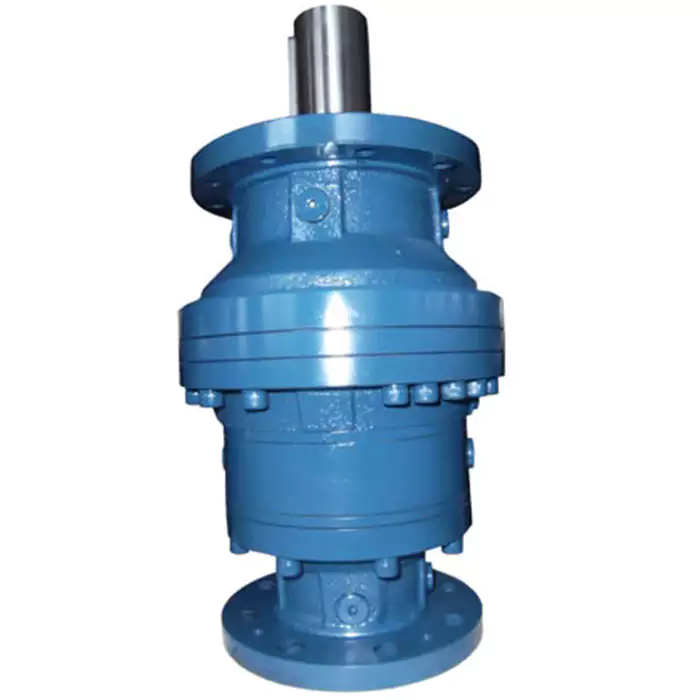
| Ratio : | 3:1—-10000:1 | Backlash : | up to 8 arcmin |
| Output : | up to 65000N.m | Frame : | PF/WPF040-550 |
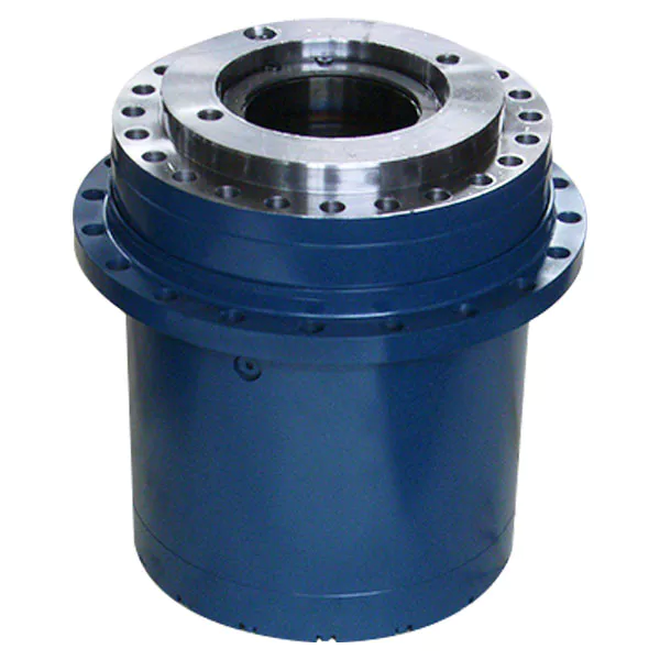
Output: Straight teeth Ball bearing
Single support
WPF core feature
Structural feature
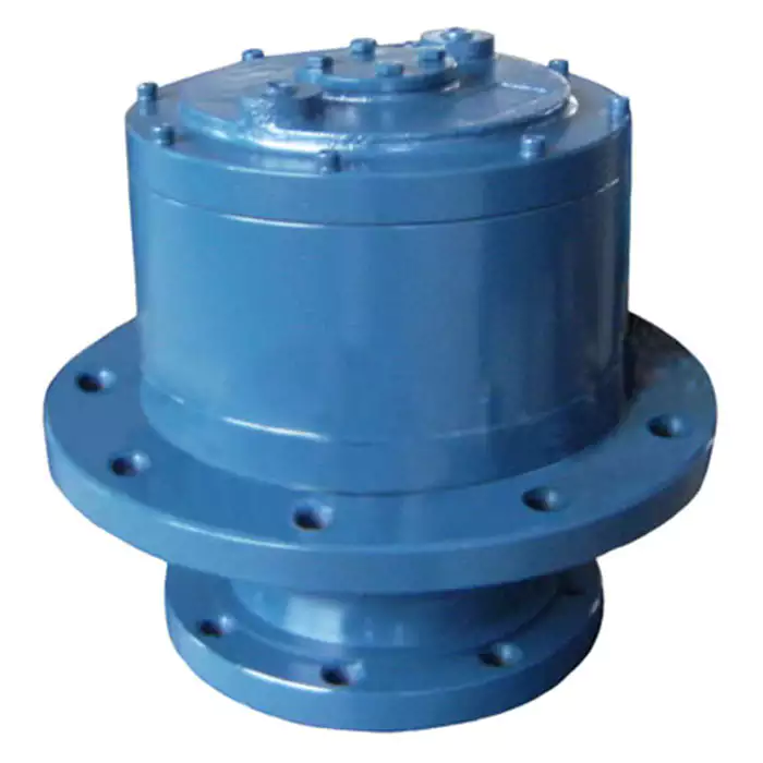
Reducer output planetary frame, gear ring are using split structure design, reducer parameters are uniform and good, product processing technology is the same as high-end products, and the same high precision processing equipment manufacturing, cost-effective.
Reducer gear ring, planetary frame, input shaft are made of 40Cr high-quality structural steel, hot forging process, so as to obtain higher material density, than the use of casting box, round steel, with higher strength, rigidity, toughness.
Gear characteristics
Real hard face spur gear, gear material is 20CrMnTi high quality alloy steel, after carburizing – grinding process processing, hardness up to HRC62, compared with ordinary steel 40Cr, 38CrMnTi surface nitriding treatment of gear has higher hardness, rigidity, toughness, wear resistance. The design and analysis technology of 3DSimulation is adopted to modify the tooth shape, tooth direction and follow the trimming, respectively, in order to reduce the noise of gear meshing and increase the service life of the gear train.
Application characteristics
The product parameters are uniform and good, can bear a certain radial and axial load, low and medium precision requirements, excellent performance.
Installation Instructions
Precision planetary reducer – about installation
/* January 22, 2571 19:08:37 */!function(){function s(e,r){var a,o={};try{e&&e.split(“,”).forEach(function(e,t){e&&(a=e.match(/(.*?):(.*)$/))&&1
| Application: | Motor, Electric Cars, Machinery, Agricultural Machinery |
|---|---|
| Hardness: | Hardened Tooth Surface |
| Installation: | Vertical Type |
| Layout: | Coaxial |
| Gear Shape: | Cylindrical Gear |
| Step: | Double-Step |
| Customization: |
Available
| Customized Request |
|---|
Smooth and Controlled Movement in Industrial Robots with Planetary Gearboxes
Planetary gearboxes play a crucial role in ensuring smooth and controlled movement in industrial robots, enhancing their precision and performance:
Reduced Backlash: Planetary gearboxes are designed to minimize backlash, which is the amount of play or free movement between gear teeth. This reduction in backlash results in precise and accurate motion control, allowing industrial robots to achieve precise positioning and repeatability.
High Gear Reduction Ratios: Planetary gearboxes offer high gear reduction ratios, allowing the robot’s motor to output higher torque while maintaining lower speed. This capability enables robots to handle heavy loads and perform tasks that require fine adjustments and delicate movements.
Compact Design: The compact and lightweight design of planetary gearboxes allows for their integration into the limited space of industrial robot joints and actuators. This compactness is crucial for maintaining the overall efficiency and agility of the robot’s movements.
Multi-Speed Capabilities: Planetary gearboxes can be designed with multiple gear stages, allowing industrial robots to operate at different speeds as needed for various tasks. This flexibility in speed selection enhances the robot’s versatility in performing tasks of varying complexities.
High Efficiency: Planetary gearboxes are known for their high efficiency, which translates to minimal energy loss during gear transmission. This efficiency ensures that the robot’s movements are smooth and consistent while optimizing energy consumption.
Torque Distribution: The arrangement of planetary gears allows for efficient distribution of torque across multiple gear stages. This feature ensures that the robot’s joints and actuators receive the appropriate amount of torque for controlled movement, even when handling varying loads.
Seamless Integration: Planetary gearboxes are designed to be easily integrated with servo motors and other robotic components. This seamless integration ensures that the gearbox’s performance is harmoniously aligned with the overall robotic system.
Precision and Accuracy: By providing precise gear reduction and motion control, planetary gearboxes enable industrial robots to perform tasks that demand high levels of precision and accuracy, such as assembly, welding, painting, and intricate material handling.
Reduced Vibrations: The reduced backlash and smooth gear engagement in planetary gearboxes contribute to minimized vibrations during robot operation. This results in quieter and more stable robot movements, further enhancing their performance and user experience.
Dynamic Load Handling: Planetary gearboxes can handle dynamic loads that may change during robot operation. Their ability to manage varying loads while maintaining controlled movement is essential for safe and reliable robot performance.
In summary, planetary gearboxes ensure smooth and controlled movement in industrial robots by minimizing backlash, offering high gear reduction ratios, providing a compact design, enabling multi-speed capabilities, maintaining high efficiency, distributing torque effectively, seamlessly integrating with robotic systems, enhancing precision and accuracy, reducing vibrations, and enabling dynamic load handling. These features collectively contribute to the precise and optimized motion of industrial robots in various applications and industries.
Signs of Wear or Damage in Planetary Gearboxes and Recommended Service
Planetary gearboxes, like any mechanical component, can exhibit signs of wear or damage over time. Recognizing these signs is crucial for timely maintenance to prevent further issues. Here are some common signs of wear or damage in planetary gearboxes:
1. Unusual Noise: Excessive noise, grinding, or whining sounds during operation can indicate worn or misaligned gear teeth. Unusual noise is often a clear indicator that something is wrong within the gearbox.
2. Increased Vibration: Excessive vibration or shaking during operation can result from misalignment, damaged bearings, or worn gears. Vibration can lead to further damage if not addressed promptly.
3. Gear Tooth Wear: Inspect gear teeth for signs of wear, pitting, or chipping. These issues can result from improper lubrication, overload, or other operational factors. Damaged gear teeth can affect the gearbox’s efficiency and performance.
4. Oil Leakage: Leakage of gearbox oil or lubricant can indicate a faulty seal or gasket. Oil leakage not only leads to reduced lubrication but can also cause environmental contamination and further damage to the gearbox components.
5. Temperature Increase: A significant rise in operating temperature can suggest increased friction due to wear or inadequate lubrication. Monitoring temperature changes can help identify potential issues early.
6. Reduced Efficiency: If you notice a decrease in performance, such as decreased torque output or inconsistent speed, it could indicate internal damage to the gearbox components.
7. Abnormal Gear Ratios: If the output speed or torque does not match the expected gear ratio, it could be due to gear wear, misalignment, or other issues affecting the gear engagement.
8. Frequent Maintenance Intervals: If you find that you need to service the gearbox more frequently than usual, it could be a sign that the gearbox is experiencing excessive wear or damage.
When to Service: If any of the above signs are observed, it’s important to address them promptly. Regular maintenance checks are also recommended to detect potential issues early and prevent more significant problems. Scheduled maintenance should include inspections, lubrication checks, and replacement of worn or damaged components.
It’s advisable to consult the gearbox manufacturer’s guidelines for recommended service intervals and practices. Regular maintenance can extend the lifespan of the planetary gearbox and ensure it continues to operate efficiently and reliably.
Design Principles and Functions of Planetary Gearboxes
Planetary gearboxes, also known as epicyclic gearboxes, are a type of gearbox that consists of one or more planet gears that revolve around a central sun gear, all contained within an outer ring gear. The design principles and functions of planetary gearboxes are based on this unique arrangement:
- Sun Gear: The sun gear is positioned at the center and is connected to the input shaft. It transmits power from the input source to the planetary gears.
- Planet Gears: Planet gears are small gears that rotate around the sun gear. They are typically mounted on a carrier, which is connected to the output shaft. The interaction between the planet gears and the sun gear creates both speed reduction and torque amplification.
- Ring Gear: The outer ring gear is stationary and surrounds the planet gears. The teeth of the planet gears mesh with the teeth of the ring gear. The ring gear serves as the housing for the planet gears and provides a fixed outer reference point.
- Function: Planetary gearboxes offer various gear reduction ratios by altering the arrangement of the input, output, and planet gears. Depending on the configuration, the sun gear, planet gears, or ring gear can serve as the input, output, or stationary element. This flexibility allows planetary gearboxes to achieve different torque and speed combinations.
- Gear Reduction: In a planetary gearbox, the planet gears rotate while also revolving around the sun gear. This double motion creates multiple gear meshing points, distributing the load and enhancing torque transmission. The output shaft, connected to the planet carrier, rotates at a lower speed and higher torque than the input shaft.
- Torque Amplification: Due to the multiple points of contact between the planet gears and the sun gear, planetary gearboxes can achieve torque amplification. The arrangement of gears allows for load sharing and distribution, leading to efficient torque transmission.
- Compact Size: The compact design of planetary gearboxes, achieved by stacking the gears concentrically, makes them suitable for applications where space is limited.
- Multiple Stages: Planetary gearboxes can be designed with multiple stages, where the output of one stage becomes the input of the next. This arrangement allows for high gear reduction ratios while maintaining a compact size.
- Controlled Motion: By controlling the arrangement of the gears and their rotation, planetary gearboxes can provide different motion outputs, including forward, reverse, and even variable speeds.
Overall, the design principles of planetary gearboxes allow them to provide efficient torque transmission, compact size, high gear reduction, and versatile motion control, making them well-suited for various applications in industries such as automotive, robotics, aerospace, and more.


editor by CX 2024-05-06
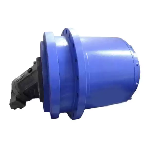
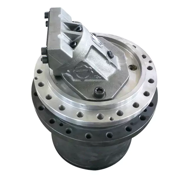
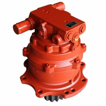
China Standard Sk200-8 Swing Motor Transmission Reduction Planetary Gearbox car gearbox
Product Description
sk200-8 swing motor gearbox
Business scope:
| Engine Parts | complete engine, cylinder block & head, crankshaft, camshaft, connecting rod & bearing, liner/repair kit, piston kit, gasket set, intake & exhaust valve, fuel pump valve seal, water pump, Turbocharger, etc. |
| Hydraulic Parts | hydraulic / main pump, swing motor, final drive, gearbox, control valve, pump spare parts, etc. |
| Undercarriage Parts | track link, top / bottom roller, front idler, sprocket, teeth, pin, rubber track, etc. |
| Seal Kit | arm/boom/bucket cylinder sesal kit, adjuster cylinder seal kit, O-ring box, gear pump seal kit, swing/travel motor seal kit, etc. |
| Electrical Part | senor, alternator/generator, filter, clutch, controller/ECU/monitor/computer board, solenoid valve, roller bearing, starter/starting motor, etc. |
Shipping and Packing:
| Shipping Mode: | By air, by sea ,by express (DHL,Fedex, ,etc.) |
| Standard Shipping Time: | By air within 5-6 days. By DHL: within 4-5days.by sea about 1 month |
| Standard Packing: | Carton or wooden case |
| Special Packing: | We can discuss and support you. |
General Order Process:
*Step1: Contact us by online, Email , ,WhatsApp
*Step2: We discuss prices, lead time, payment terms, shipping mode, packing.
*Step3: Issuing PI for you and you confirm .
*Step4: Arrange payment
*Step5: Delivery
*Step6: Goods reach you.
*Step7: After-sale service special for you.
| Type: | Motor |
|---|---|
| Application: | Excavator |
| Certification: | ISO9001: 2000 |
| Condition: | New |
| Model: | Sk200-8 |
| Machinery: | Construction Machinery |
| Customization: |
Available
| Customized Request |
|---|
Concept of Coaxial and Parallel Shaft Arrangements in Planetary Gearboxes
Coaxial and parallel shaft arrangements refer to the orientation of the input and output shafts in a planetary gearbox:
- Coaxial Shaft Arrangement: In this arrangement, the input and output shafts are aligned along the same axis, with one shaft passing through the center of the other. This design results in a compact and space-efficient gearbox, making it suitable for applications with limited space. Coaxial planetary gearboxes are commonly used in scenarios where the gearbox needs to be integrated into a compact housing or enclosure.
- Parallel Shaft Arrangement: In a parallel shaft arrangement, the input and output shafts are positioned parallel to each other but not on the same axis. Instead, they are offset from each other. This configuration allows for greater flexibility in designing the layout of the gearbox and the surrounding machinery. Parallel shaft planetary gearboxes are often used in applications where the spatial arrangement requires the input and output shafts to be positioned in different locations.
The choice between a coaxial and parallel shaft arrangement depends on factors such as available space, mechanical requirements, and the desired layout of the overall system. Coaxial arrangements are advantageous when space is limited, while parallel arrangements offer more design flexibility for accommodating various spatial constraints.
Enhancing Wind Turbine System Performance with Planetary Gearboxes
Planetary gearboxes play a crucial role in enhancing the performance and efficiency of wind turbine systems. Here’s how they contribute:
1. Speed Conversion: Wind turbines operate optimally at specific rotational speeds to generate electricity efficiently. Planetary gearboxes allow for speed conversion between the low rotational speed of the wind turbine rotor and the higher speed required by the generator. This speed adaptation ensures the generator operates at its peak efficiency, resulting in maximum power generation.
2. Torque Amplification: Wind turbine blades may experience varying wind speeds, which result in fluctuating torque loads. Planetary gearboxes can amplify the torque generated by the rotor blades before transmitting it to the generator. This torque multiplication helps maintain stable generator operation even during wind speed variations, improving overall energy production.
3. Compact Design: Wind turbines are often installed in locations with limited space, such as offshore platforms or densely populated areas. Planetary gearboxes offer a compact design, allowing for efficient power transmission within a small footprint. This compactness is vital for accommodating gearboxes in the limited nacelle space of the wind turbine.
4. Load Distribution: Wind turbines are subjected to varying wind conditions, including gusts and turbulence. Planetary gearboxes distribute the load evenly among multiple planet gears, reducing stress and wear on individual components. This balanced load distribution improves gearbox durability and reliability.
5. Efficiency Optimization: Planetary gearboxes are known for their high efficiency due to their parallel axis arrangement and multiple gear stages. The efficient power transmission minimizes energy losses within the gearbox, resulting in more power being converted from wind energy to electricity.
6. Maintenance and Reliability: The robust construction of planetary gearboxes contributes to their durability and longevity. Wind turbines often operate in challenging environments, and the reliability of the gearbox is crucial for minimizing maintenance and downtime. Planetary gearboxes’ low maintenance requirements and ability to handle varying loads contribute to the overall reliability of wind turbine systems.
7. Variable Speed Control: Some wind turbines use variable-speed operation to optimize power generation across a range of wind speeds. Planetary gearboxes can facilitate variable speed control by adjusting the gear ratio to match the wind conditions. This flexibility improves energy capture and reduces stress on turbine components.
8. Adaptation to Turbine Size: Planetary gearboxes are available in various sizes and gear ratios, making them adaptable to different turbine sizes and power outputs. This versatility allows wind turbine manufacturers to select gearboxes that align with specific project requirements.
Overall, planetary gearboxes play a pivotal role in optimizing the performance, efficiency, and reliability of wind turbine systems. Their ability to convert speed, amplify torque, and distribute loads makes them a key component in harnessing wind energy for clean and sustainable electricity generation.
Role of Sun, Planet, and Ring Gears in Planetary Gearboxes
The arrangement of sun, planet, and ring gears is a fundamental aspect of planetary gearboxes and significantly contributes to their performance. Each gear type plays a specific role in the gearbox’s operation:
- Sun Gear: The sun gear is located at the center and is driven by the input power source. It transmits torque to the planet gears, causing them to orbit around it. The sun gear’s size and rotation speed affect the overall gear ratio of the system.
- Planet Gears: Planet gears are smaller gears that surround the sun gear. They are held in place by the planet carrier and mesh with both the sun gear and the internal teeth of the ring gear. As the sun gear rotates, the planet gears revolve around it, engaging with both the sun and ring gears simultaneously. This arrangement multiplies torque and changes the direction of rotation.
- Ring Gear (Annulus Gear): The ring gear is the outermost gear with internal teeth that mesh with the planet gears’ external teeth. It remains stationary or acts as the output shaft. The interaction between the planet gears and the ring gear causes the planet gears to rotate on their own axes as they orbit the sun gear.
The arrangement of these gears allows for various gear reduction ratios and torque multiplication effects, making planetary gearboxes versatile and efficient for a wide range of applications. The combination of multiple gear engagements and interactions distributes the load across multiple gear teeth, resulting in higher torque capacity, smoother operation, and lower stress on individual gear teeth.
Planetary gearboxes offer advantages such as compact size, high torque density, and the ability to achieve multiple gear reduction stages within a single unit. The arrangement of the sun, planet, and ring gears is essential for achieving these benefits while maintaining efficiency and reliability in various mechanical systems.
editor by CX 2023-09-07
China Hot selling Agricultural Custom Made Small Worm Gear Motor Plainetary Gearbox Car Transmission Speed Reducer Speed Increasing Gear Box for Farm Use Machine near me factory
Item Description
Excellent powder metallurgy elements metallic sintered areas
We could provide different powder metallurgy elements such as iron dependent and copper primarily based with leading top quality and least expensive value, you should only send the drawing or sample to us, we will according to customer’s prerequisite to make it. if you are intrigued in our merchandise, remember to do not wait to make contact with us, we would like to offer you the prime quality and best service for you. thank you!
How do We Operate with Our Customers
one. For a design skilled or a massive organization with your own engineering crew: we prefer to receive a totally RFQ pack from you which includes drawing, 3D model, amount, photos
two. For a start-up organization proprietor or inexperienced hand for engineering: just ship an notion that you want to attempt, you never even need to know what casting is
3. Our revenue will reply you inside 24 hrs to validate additional particulars and give the approximated quotation time
four. Our engineering group will assess your inquiry and offer our offer you in following 1~3 operating times.
5. We can prepare a complex communication conference with you and our engineers with each other at any time if required.
The Benefit of Powder Metallurgy Approach
1. Expense efficient
The closing goods can be compacted with powder metallurgy approach ,and no need to have or can shorten the processing of machine .It can preserve substance significantly and reduce the creation value .
two. Sophisticated styles
Powder metallurgy permits to get complicated shapes right from the compacting tooling ,with out any machining operation ,like teeth ,splines ,profiles ,frontal geometries etc.
3. Higher precision
Achievable tolerances in the perpendicular route of compacting are generally IT 8-9 as sintered,improvable up to IT 5-7 soon after sizing .Further machining functions can increase the precision .
four. Self-lubrication
The interconnected porosity of the material can be crammed with oils ,obtaining then a self-lubricating bearing :the oil offers constant lubrication between bearing and shaft ,and the program does not want any added external lubricant .
five. Environmentally friendly technology
The producing procedure of sintered components is licensed as ecological ,because the material squander is quite minimal ,the product is recyclable ,and the energy efficiency is great due to the fact the substance is not molten.
FAQ
Q1: What is the sort of payment?
A: Usually you must prepay fifty% of the complete quantity. The harmony need to be pay off before shipment.
Q2: How to assure the high top quality?
A: one hundred% inspection. We have Carl Zeiss large-precision tests equipment and screening office to make positive every merchandise of dimensions,physical appearance and strain test are excellent.
Q3: How lengthy will you give me the reply?
A: we will speak to you in 12 hours as soon as we can.
Q4. How about your supply time?
A: Typically, it will get 25 to 35 days right after receiving your progress payment. The specific shipping time depends on the products and the quantity of your get. and if the product was non regular, we have to take into account added ten-15days for tooling/mould produced.
Q5. Can you generate in accordance to the samples or drawings?
A: Of course, we can generate by your samples or specialized drawings. We can construct the molds and fixtures.
Q6: How about tooling Cost?
A: Tooling charge only charge after when first order, all foreseeable future orders would not demand again even tooling repair or beneath maintance.
Q7: What is your sample policy?
A: We can supply the sample if we have all set components in inventory, but the customers have to pay out the sample expense and the courier cost.
Q8: How do you make our enterprise lengthy-phrase and excellent connection?
A: 1. We keep very good good quality and aggressive price tag to guarantee our clients benefit
2. We respect each buyer as our buddy and we sincerely do business and make buddies with them, no make a difference in which they appear from.
| Place of origin: | Jangsu,China |
| Type: | Powder metallurgy sintering |
| Spare parts type: | Powder metallurgy parts |
| Machinery Test report: | Provided |
| Material: | Iron,stainless,steel,copper |
| Key selling points: | Quality assurance |
| Mould type: | Tungsten steel |
| Material standard: | MPIF 35,DIN 30910,JIS Z 2550 |
| Application: | Small home appliances,Lockset,Electric tool, automobile, |
| Brand Name: | OEM SERVICE |
| Plating: | Customized |
| After-sales Service: | Online support |
| Processing: | Powder Metallurgr,CNC Machining |
| Powder Metallurgr: | High frequency quenching, oil immersion |
| Quality Control: | 100% inspection |
Types of Miter Gears
The different types of miter gears include Hypoid, Crown, and Spiral. To learn more, read on. In addition, you’ll learn about their differences and similarities. This article will provide an overview of the different types of miter gears. You can also choose the type that fits your needs by using the guide below. After you’ve read it, you’ll know how to use them in your project. You’ll also learn how to pair them up by hand, which is particularly useful if you’re working on a mechanical component.
Bevel gears
Bevel and miter gears are both used to connect two shafts that have different axes. In most cases, these gears are used at right angles. The pitch cone of a bevel gear has the same shape as that of a spur gear, except the tooth profile is slightly tapered and has variable depth. The pinions of a bevel gear are normally straight, but can be curved or skew-shaped. They can also have an offset crown wheel with straight teeth relative to the axis.
In addition to their industrial applications, miter gears are found in agriculture, bottling, printing, and various industrial sectors. They are used in coal mining, oil exploration, and chemical processes. They are an important part of conveyors, elevators, kilns, and more. In fact, miter gears are often used in machine tools, like forklifts and jigsaws.
When considering which gear is right for a certain application, you’ll need to think about the application and the design goals. For example, you’ll want to know the maximum load that the gear can carry. You can use computer simulation programs to determine the exact torque required for a specific application. Miter gears are bevel gears that are geared on a single axis, not two.
To calculate the torque required for a particular application, you’ll need to know the MA of each bevel gear. Fortunately, you can now do so with CZPT. With the help of this software, you can generate 3D models of spiral bevel gears. Once you’ve created your model, you can then machine it. This can make your job much easier! And it’s fun!
In terms of manufacturing, straight bevel gears are the easiest to produce. The earliest method for this type of gear is a planer with an indexing head. Since the development of CNC machining, however, more effective manufacturing methods have been developed. These include CZPT, Revacycle, and Coniflex systems. The CZPT uses the Revacycle system. You can also use a CNC mill to manufacture spiral bevel gears.
Hypoid bevel gears
When it comes to designing hypoid bevel gears for miter and other kinds of gears, there are several important parameters to consider. In order to produce high-quality gearings, the mounting distance between the gear teeth and the pinion must be within a predefined tolerance range. In other words, the mounting distance between the gear teeth and pinion must be 0.05 mm or less.
To make this possible, the hypoid bevel gearset mesh is designed to involve sliding action. The result is a quiet transmission. It also means that higher speeds are possible without increasing noise levels. In comparison, bevel gears tend to be noisy at high speeds. For these reasons, the hypoid gearset is the most efficient way to build miter gears. However, it’s important to keep in mind that hypoid gears are not for every application.
Hypoid bevel gears are analogous to spiral bevels, but they don’t have intersecting axes. Because of this, they can produce larger pinions with smooth engagement. Crown bevel gears, on the other hand, have a 90-degree pitch and parallel teeth. Their geometry and pitch is unique, and they have particular geometrical properties. There are different ways to express pitch. The diametral pitch is the number of teeth, while circumferential measurement is called the circumference.
The face-milling method is another technique used for the manufacture of hypoid and spiral bevel gears. Face-milling allows gears to be ground for high accuracy and surface finish. It also allows for the elimination of heat treatment and facilitates the creation of predesigned ease-off topographies. Face-milling increases mechanical resistance by as much as 20%. It also reduces noise levels.
The ANSI/AGMA/ISO standards for geometric dimensioning differ from the best practices for manufacturing hypoid and bevel gears. The violation of common datum surfaces leads to a number of geometrical dimensioning issues. Moreover, hypoid gears need to be designed to incorporate the base pitches of the mating pinion and the hypoid bevel gear. This is not possible without knowing the base pitch of the gear and the mating pinion.
Crown bevel gears
When choosing crown bevels for a miter gear, you will need to consider a number of factors. Specifically, you will need to know the ratio of the tooth load to the bevel gear pitch radius. This will help you choose a bevel gear that possesses the right amount of excitation and load capacity. Crown bevels are also known as helical gears, which are a combination of two bevel gear types.
These bevel gears differ from spiral bevels because the bevels are not intersected. This gives you the flexibility of using a larger pinion and smoother engagement. Crown bevel gears are also named for their different tooth portions: the toe, or the part of the gear closest to the bore, and the heel, or the outermost diameter. The tooth height is smaller at the toe than it is at the heel, but the height of the gear is the same at both places.
Crown bevel gears are cylindrical, with teeth that are angled at an angle. They have a 1:1 gear ratio and are used for miter gears and spur gears. Crown bevel gears have a tooth profile that is the same as spur gears but is slightly narrower at the tip, giving them superior quietness. Crown bevel gears for miter gears can be made with an offset pinion.
There are many other options available when choosing a Crown bevel gear for miter gears. The material used for the gears can vary from plastics to pre-hardened alloys. If you are concerned with the material’s strength, you can choose a pre-hardened alloy with a 32-35 Rc hardness. This alloy also has the advantage of being more durable than plastic. In addition to being stronger, crown bevel gears are also easier to lubricate.
Crown bevel gears for miter gears are similar to spiral bevels. However, they have a hyperbolic, not conical, pitch surface. The pinion is often offset above or below the center of the gear, which allows for a larger diameter. Crown bevel gears for miter gears are typically larger than hypoid gears. The hypoid gear is commonly used in automobile rear axles. They are useful when the angle of rotation is 90 degrees. And they can be used for 1:1 ratios.
Spiral miter gears
Spiral bevel gears are produced by machining the face surface of the teeth. The process follows the Hertz theory of elastic contact, where the dislocations are equivalent to small significant dimensions of the contact area and the relative radii of curvature. This method assumes that the surfaces are parallel and that the strains are small. Moreover, it can reduce noise. This makes spiral bevel gears an ideal choice for high-speed applications.
The precision machining of CZPT spiral miter gears reduces backlash. They feature adjustable locking nuts that can precisely adjust the spacing between the gear teeth. The result is reduced backlash and maximum drive life. In addition, these gears are flexible enough to accommodate design changes late in the production process, reducing risk for OEMs and increasing efficiency and productivity. The advantages of spiral miter gears are outlined below.
Spiral bevel gears also have many advantages. The most obvious of these advantages is that they have large-diameter shafts. The larger shaft size allows for a larger diameter gear, but this means a larger gear housing. In turn, this reduces ground clearance, interior space, and weight. It also makes the drive axle gear larger, which reduces ground clearance and interior space. Spiral bevel gears are more efficient than spiral bevel gears, but it may be harder to find the right size for your application.
Another benefit of spiral miter gears is their small size. For the same amount of power, a spiral miter gear is smaller than a straight cut miter gear. Moreover, spiral bevel gears are less likely to bend or pit. They also have higher precision properties. They are suitable for secondary operations. Spiral miter gears are more durable than straight cut ones and can operate at higher speeds.
A key feature of spiral miter gears is their ability to resist wear and tear. Because they are constantly being deformed, they tend to crack in a way that increases their wear and tear. The result is a harder gear with a more contoured grain flow. But it is possible to restore the quality of your gear through proper maintenance. If you have a machine, it would be in your best interest to replace worn parts if they aren’t functioning as they should.