Product Description
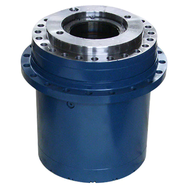
Wirtgen part.no 79353 gearbox and gear reduction 79354
WIRGTEN 705C2HS571B64J0HIV 7649 bonfiglioli gearbox
Product Description
11ton-13ton Dual Drum Vibratory Roller XD111 XD121 XD131
705C2H33C53J0HJVAT CAT PAVER DRIVE GEARBOX
Wirtgen GEARBOX 257128 257129 used on the Wirtgen cold milling machines 2228352 15716
Ходовой редуктор Wirtgen,гидромотор фрезы Wirtgen W series
| Machine type | Series range | Version advance drive | Gearbox and sealing kits | |||
| Drive gearbox | ||||||
| Gearbox | Sealing kit cpl. |
Face seal | Brake disc | |||
| Wirtgen W 350 | 0001 – 0058 | 46176 | 193511 | 53141 | 193482 | |
| 0059 – 0265 | 76491 | 88219 | 1 0571 9 | 193484 | ||
| 0266 – 9999 | ||||||
| Wirtgen W 35 | 0001 – 9999 | 76491 | 88219 | 1 0571 9 | 193484 | |
| Wirtgen W 35 DC | 0001 – 9999 | One wheel drive front | 76491 | 88219 | 1 0571 9 | 193484 |
| Four wheel drive front | 79354 | |||||
| Four wheel drive rear | 18571 | 193573 | ||||
| Wirtgen W 500 | 0112 – 5717 | Front | 53344 | 45665 | ||
| Rear left and right | 53345 | 193550 | 45665 | 144901 | ||
| 5718 – 9999 | Front | 53344 | 45665 | |||
| Rear left and right | 53345 | 193550 | 45665 | 144901 | ||
| Wirtgen W 50 08.05 | 0001 – 5710 | 3-wheel front | 170611 | 185046 | ||
| 4-wheel front | 170695 | |||||
| 5711 – 9999 | 3-wheel front | 186032 | ||||
| 4-wheel front | 186031 | 185045 | ||||
| 0001 – 0067 | Right rear | 17571 | ||||
| Left rear | 170610 | |||||
| 0068 – 5710 | Rear left and right | 170610 | ||||
| 5711 – 9999 | Right rear | 186095 | ||||
| Left rear | 186030 | |||||
| Wirtgen W 50 10.05 | 0001 – 9999 | 3-wheel front | 186032 | 185046 | ||
| 4-wheel front | 186031 | 185045 | ||||
| Right rear | 186095 | |||||
| Left rear | 186030 | |||||
| Wirtgen W 50 DC | 0001 – 0099 | 3-wheel front | 170615 | 185046 | ||
| 4-wheel front | 170696 | 185045 | ||||
| 5710 – 9999 | 3-wheel front | 76490 | 1 0571 9 | |||
| 4-wheel front | 187884 | |||||
| 0001 – 0050 | Right rear | 170613 | 185045 | |||
| Left rear | 170614 | |||||
| 0051 – 0099 | Rear left and right | 170614 | ||||
| 5710 – 9999 | Rear left and right | 186033 | ||||
| Wirtgen W 600 DC, W 1000 L |
0001 – 9999 | 3-wheel front | 76490 | 1 0571 9 | ||
| 3-wheel rear | 76491 | 88219 | 1 0571 9 | 193484 | ||
| 4-wheel front | 79353 | 1 0571 9 | ||||
| 4-wheel rear | 79354 | 88219 | 1 0571 9 | 193484 | ||
| Machine type | Series range | Version advance drive | Gearbox and sealing kits | |||
| Drive gearbox | ||||||
| Gearbox | Sealing kit cpl. |
Face seal | Brake disc | |||
| Wirtgen W 1000 | 0001 – 571 | Front and rear | 46176 | 193511 | 53141 | 193482 |
| 0011 – 571 | Front and rear | 76491 | 88219 | 1 0571 9 | 193484 | |
| Wirtgen W 60, W 100 | 0001 – 9999 | 3-wheel front | 76490 | 1 0571 9 | ||
| 3-wheel rear | 76491 | 88219 | 1 0571 9 | 193484 | ||
| 4-wheel front | 79353 | 1 0571 9 | ||||
| 4-wheel rear | 79354 | 88219 | 1 0571 9 | 193484 | ||
| Wirtgen W 1000 F, W 1200 F, W 1300 F 07.10 |
0001 – 0038 | Wheel machine | 76491 | 88219 | 1 0571 9 | 193484 |
| Chain machine | 121257 | |||||
| 0039 – 0149 | Wheel machine | 76491 | ||||
| Chain machine | 121257 | |||||
| 0150 – 0571 | Wheel machine | 76491 | ||||
| Chain machine | 121257 | |||||
| 0571 – 9999 | Wheel machine | 76491 | ||||
| Chain machine | 121257 | |||||
| Wirtgen W 100 F, W 120 F, W 130 F |
0001 – 9999 | Wheel machine | 76491 | 88219 | 1 0571 9 | 193484 |
| Chain machine | 121257 | |||||
| 1300 – 2000 DC | 0001 – 0058 | Front | 76491 | 88219 | 1 0571 9 | 193484 |
| Rear | 76490 | 1 0571 9 | ||||
| 0059 – 9999 | Front | 76491 | 88219 | 1 0571 9 | 193484 | |
| Rear | 76490 | 1 0571 9 | ||||
| Wirtgen W 1500, W 1900 |
0001 – 9998 | Front | 76491 | 88219 | 1 0571 9 | 193484 |
| Rear | 76490 | 1 0571 9 | ||||
| 9998 – 9999 | Front | 257129 | 88219 | 1 0571 9 | 193484 | |
| Rear | 257128 | 1 0571 9 | ||||
| Wirtgen W 150 | 0001 – 9999 | Front and rear | 121257 | 88219 | 1 0571 9 | 193484 |
| Wirtgen W 2000 | 0001 – 9999 | Front | 15716 | 193547 | 157184 | 123648 |
| Rear | 15715 | 157184 | ||||
| Wirtgen 2100 DC | 0001 – 0041 | Front | 34959 | 53873 | 5571 | |
| Rear | 34958 | 53872 | 5571 | 4571 | ||
| 0042 – 0120 | Front | 45869 | 5571 | |||
| Rear | 45868 | 53873 | 5571 | 4571 | ||
| 0121 – 0269 | Front | 72844 | 5571 | |||
| Rear | 72842 | 53873 | 5571 | 4571 | ||
| 5710 – 0345 | Front | 85960 | 15718 | |||
| Rear | 85961 | 15713 | 15718 | 15712 | ||
| 0346 – 9999 | Front | 85960 | 15718 | |||
| Rear | 85961 | 15713 | 15718 | 15712 | ||
| Machine type | Series range | Version advance drive | Gearbox and sealing kits | |||
| Drive gearbox | ||||||
| Gearbox | Sealing kit cpl. |
Face seal | Brake disc | |||
| Wirtgen W 2100 | 0001 – 0091 | Front | 139571 | 193512 | 156316 | 156326 |
| Rear | 139571 | 156316 | ||||
| 0092 – 0117 | Front | 139571 | 193512 | 156316 | 156326 | |
| Rear | 139571 | 156316 | ||||
| 0118 – 9999 | Front | 139571 | 193512 | 156316 | 156326 | |
| Rear | 139571 | 156316 | ||||
| Wirtgen W 2200 | 0001 – 5718 | Front | 117831 | 193514 | 144398 | 144305 |
| Rear | 117830 | 144398 | ||||
| 5719 – 9999 | Front | 117831 | 193514 | 144398 | 144305 | |
| Rear | 117830 | 144398 | ||||
| Wirtgen WR 2000 | 0001 – 9999 | 166995 | 193513 | 181697 | 181695 | |
| Wirtgen WR 2400 | 0001 – 0003 | 80571 | 133331 | 51433 | 132160 | |
| 0004 – 9999 | 188848 | 2063096 | 181697 | 156326 | ||
| Wirtgen WR 2500 | 0001 – 5719 | 80571 | 51433 | |||
| 0110 – 9999 | 80571 | 133331 | 51433 | 132160 | ||
| Wirtgen WR 2500 S | 0001 – 9999 | 80571 | 133331 | 51433 | 132160 | |
| Wirtgen W 350 | 0001 – 0058 | 66627 | 84811 | 86496 | ||
| 0059 – 0265 | 66627 | |||||
| 0266 – 9999 | 101979 | |||||
| Wirtgen W 35 | 0001 – 9999 | 101979 | 84811 | 86496 | ||
| Wirtgen W 35 DC | 0001 – 5719 | 18 0571 | 186608 | 186527 | ||
| 5710 – 9999 | 257190 | |||||
| Wirtgen W 500 | 0112 – 5717 | 64547 | ||||
| 5718 – 9999 | 72605 | 37514 | ||||
| Machine type | Series range | Gearbox and sealing kits | ||||
| Milling drum gearbox | Pump splitter gearbox | |||||
| Gearbox | Sealing ring | Face seal | Gearbox | Sealing ring | ||
| Wirtgen W 50 08.05 | 0001 – 9999 | 168008 | 7762 | 186527 | ||
| Wirtgen W 50 10.05 | 0001 – 0123 | 168008 | 7762 | 186527 | ||
| 0124 – 9999 | 2086584 | 7762 | 186527 | |||
| Wirtgen W 50 DC | 0001 – 9999 | 164068 | 7762 | 186528 | ||
| Wirtgen W 600 DC | 0001 – 9999 | 92668 | 79827 | 155375 | ||
| Wirtgen W 60 | 0001 – 9999 | 92668 | 79827 | 155375 | ||
| Wirtgen W 1000 L | 0001 – 9999 | 70197 | 79827 | 51433 | ||
| Wirtgen W 1000 | 0001 – 571 | 70197 | 79827 | 51433 | ||
| Wirtgen W 100 | 0001 – 9999 | 70197 | 79827 | 51433 | ||
| Wirtgen W 1000 F, W 1200 F, W 1300 F |
0001 – 0038 | 90127 | 79827 | 51433 | 90054 | 25105* 139936 |
| 0039 – 0131 | 90127 | 79827 | 51433 | 12970 | ||
| 0132 – 0149 | 90127 | 79827 | 51433 | 138848 | 139937* 139938 |
|
| 0150 – 0571 | 90127 | 79827 | 51433 | 138193 | 25105* 139936 |
|
| 0571 – 0869 | 90127 | 79827 | 51433 | 155735 | ||
| 0571 – 9999 | 90127 | 79827 | 51433 | 2044777 | ||
| Wirtgen W 100 F, W 120 F, W 130 F |
0001 – 9999 | 190070 190073 FCS |
25105 | 51433 | 195711 | 139936* 2061878 |
| Wirtgen 1300 – 2000 DC | 0001 – 0058 | 52364 | 73747 | 51433 | 36963 | 84811 |
| 0059 – 9999 | 87709 | 15714 | ||||
| Wirtgen W 1500 | 0001 – 9999 | 87708 | 73747 | 15714 | 36963 | 84811 |
| Wirtgen W 1900 | 0001 – 5713 | 87708 | 73747 | 15714 | 36963 | 84811 |
| 5714 – 9999 | 126869 | 155158 | 129617 | |||
| Wirtgen W 2000 | 0001 – 9999 | 126869 | 155158 | 129617 | 113038 | 25106* 82052 |
| Wirtgen 2100 DC | 0042 – 0345 | 42133 | 37502 | 36963 | 84811 | |
| 0346 – 9999 | 157114 | 63606 | 123738 | |||
| Wirtgen W 2100 | 0001 – 0091 | 136986 | 155158 | 154190 | 14 0571 | 25106* 82052 |
| 0092 – 0117 | 172841 | |||||
| 0118 – 9999 | 177662 | |||||
| Wirtgen W 2200 | 0001 – 5718 | 112600 | 7750 | 161345 | 113042 | 25106* 178531 |
| 5719 – 9999 | 180038 | 45451 | ||||
| Wirtgen WR 2000 | 0001 – 9999 | 166990 | 191906 | 171519 | 25106* 82052 |
|
| Wirtgen WR 2400 | 0001 – 9999 | 166990 | 191906 | 195712 | 25106* 82052 |
|
| Wirtgen WR 2500 | 0001 – 0058 | 80018 | 11217 | 36963 | 84811 | |
| 0059 – 5719 | 99913 | 133332 | ||||
| 0110 – 5712 | 99913 | 133332 | 11217 | 1 0571 7 | ||
| 5713 – 0309 | 130940 | 144443 | 144440 | |||
| 571 – 9999 | 156488 | 144443 | ||||
| Wirtgen WR 2500 S | 0001 – 9999 | 156488 | 144443 | 144440 | 1 0571 7 | 84811 |
| Wirtgen WS 2200, WS 2500 | 0001 – 9999 | 191906 | 7765 | 106467 | ||
Two light-duty tandem vibratory rollers
Dual Drum Vibratory Roller
Cummins engine
| Type | XD111 | XD121 | XD131 | |
| Working mass(kg) | 11230 | 12300 | 13080 | |
| Mass distributed on front drum(kg) | 5670 | 6210 | 6540 | |
| Mass distributed on rear drum(kg) | 5560 | 6090 | 6540 | |
| Static linear load on front drum(N/cm) | 292 | 286 | 301 | |
| Static linear load on rear drum(N/cm) | 287 | 280 | 301 | |
| Speed range(km/h) | 0-10 | 0-10 | 0-10 | |
| Theoretical gradeability(%) | 30 | 30 | 30 | |
| Min. inner/outer turning radius(mm) | 4000/5900 | 3870/6000 | 3870/6000 | |
| Crab-walking distance (mm) | 200 | 200 | 200 | |
| Min. ground clearance(mm) | 420 | 420 | 420 | |
| Wheel base (mm) | 4000 | 4000 | 4000 | |
| Steering angle(±) | 46 | 46 | 46 | |
| Swinging angle(±) | 12 | 12 | 12 | |
| Vibrating frequency(HZ) | 30-48 | 30-45 | 30-45 | |
| Nominal amplitude(mm) | 0.41/0.8 | 0.41/0.8 | 0.4/0.72 | |
| Centrifugal force(kn) | 66/133 | 70/140 | 82/150 | |
| Model and manufacturer | COMMINS 483.9 | |||
| Rated rotating speed(t/min) | 2200 | 2200 | 2200 | |
| Rated Power(KW)93 | 93 | 93 | 93 | |
| Rated oil wear (g. kw/h)229 | 229 | 229 | 229 | |
| Water tank capacity(L) | 2*450 | 2*450 | 2*450 | |
| Fuel tank capacity(L) | 200 | 220 | 220 | |
Cheapest Price Hydraulic Single Drum Vibratory Compactor Xs142j in Philippines
Xcm Hydraulic Single-Drum Vibratory Rollers Capacity 14 Tons Xs142j in Indonesia
Compacting Price CZPT Single Drum Road Roller Xs142j
Brand New CZPT 14t Single Drum Vibratory Road Roller Xs142j
12 Ton Hydraulic Tandem Vibratory Roller Compactor Xd122
Liugong 12 Ton Double Drum Road Roller Price Clg6212e
Xcm 18 Ton Road Roller Xs182j
Sdlg 14 Ton Vibratory Road Roller Compactor RS8140
2017 New Price CZPT Pneumatic Tire Road Roller Clg630r
14 Tons Double Drum Vibratory Roller Xd142
Hot Sale Road Compactor 10 Ton Tandem Vibratory Roller Xd102
3 Ton CZPT Popular Vibratory Mini Road Roller (Ltc203)
11 Ton Hydraulic Double Drum Road Roller Xd111e
12 Ton Hydraulic Double Drum Road Roller Xd121e
11300kg Double Drum Roller CZPT Xd111e
11 Tons Hydraulic Vibratory Double Drum Compactor Xd111e
Liugong Vibration Road Roller Capacity Clg614
Cheap Price Xihu (West Lake) Dis.n 16ton Road Roller Yz16-7 Sale
Xs202j 20 Ton Single Drum Vibratory Road Roller
11 Ton Vibratory Double Drum Road Roller Xd111e
Product Groups
Wheel Loader
Truck Crane
Excavator
Bulldozer
Motor Grader
Road Roller
Backhoe Loader
Heavy Truck
Crawler Crane
Tower crane
| Application: | Motor |
|---|---|
| Function: | Distribution Power |
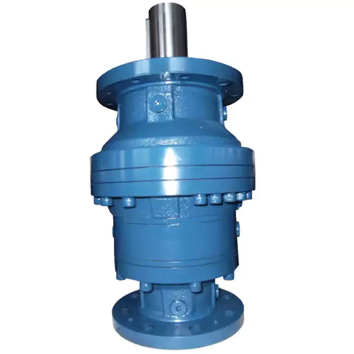
| Layout: | Three-Ring |
| Hardness: | Hardened Tooth Surface |
| Installation: | Torque Arm Type |
| Step: | Three-Step |
| Customization: |
Available
| Customized Request |
|---|
Challenges in Achieving High Gear Ratios with Compactness in Planetary Gearboxes
Designing planetary gearboxes with high gear ratios while maintaining compactness presents several challenges:
- Space Constraints: As the gear ratio increases, the number of gear stages required also increases. This can lead to larger gearbox sizes, which may be challenging to accommodate in applications with limited space.
- Bearing Loads: Higher gear ratios often result in increased loads on the bearings and other components due to the redistribution of forces. This can impact the durability and lifespan of the gearbox.
- Efficiency: Each gear stage introduces losses due to friction and other factors. With multiple stages, the overall efficiency of the gearbox can decrease, affecting its energy efficiency.
- Complexity: Achieving high gear ratios can require complex gear arrangements and additional components, which can lead to increased manufacturing complexity and costs.
- Thermal Effects: Higher gear ratios can lead to greater heat generation due to increased friction and loads. Managing thermal effects becomes crucial to prevent overheating and component failure.
To address these challenges, gearbox designers use advanced materials, precise machining techniques, and innovative bearing arrangements to optimize the design for both compactness and performance. Computer simulations and modeling play a critical role in predicting the behavior of the gearbox under different operating conditions, helping to ensure reliability and efficiency.
Considerations for Selecting Size and Gear Materials in Planetary Gearboxes
Choosing the appropriate size and gear materials for a planetary gearbox is crucial for optimal performance and reliability. Here are the key considerations:
1. Load and Torque Requirements: Evaluate the anticipated load and torque that the gearbox will experience in the application. Select a gearbox size that can handle the maximum load without exceeding its capacity, ensuring reliable and durable operation.
2. Gear Ratio: Determine the required gear ratio to achieve the desired output speed and torque. Different gear ratios are achieved by varying the number of teeth on the gears. Select a gearbox with a suitable gear ratio for your application’s requirements.
3. Efficiency: Consider the efficiency of the gearbox, which is influenced by factors such as gear meshing, bearing losses, and lubrication. A higher efficiency gearbox minimizes energy losses and improves overall system performance.
4. Space Constraints: Evaluate the available space for installing the gearbox. Planetary gearboxes offer compact designs, but it’s essential to ensure that the selected size fits within the available area, especially in applications with limited space.
5. Material Selection: Choose suitable gear materials based on factors like load, speed, and operating conditions. High-quality materials, such as hardened steel or specialized alloys, enhance gear strength, durability, and resistance to wear and fatigue.
6. Lubrication: Proper lubrication is critical for reducing friction and wear in the gearbox. Consider the lubrication requirements of the selected gear materials and ensure the gearbox is designed for efficient lubricant distribution and maintenance.
7. Environmental Conditions: Assess the environmental conditions in which the gearbox will operate. Factors such as temperature, humidity, and exposure to contaminants can impact gear material performance. Choose materials that can withstand the operating environment.
8. Noise and Vibration: Gear material selection can influence noise and vibration levels. Some materials are more adept at dampening vibrations and reducing noise, which is essential for applications where quiet operation is crucial.
9. Cost: Consider the budget for the gearbox and balance the cost of materials, manufacturing, and performance requirements. While high-quality materials may increase initial costs, they can lead to longer gearbox lifespan and reduced maintenance expenses.
10. Manufacturer’s Recommendations: Consult with gearbox manufacturers or experts for guidance on selecting the appropriate size and gear materials. They can provide insights based on their experience and knowledge of various applications.
Ultimately, the proper selection of size and gear materials is vital for achieving reliable, efficient, and long-lasting performance in planetary gearboxes. Taking into account load, gear ratio, materials, lubrication, and other factors ensures the gearbox meets the specific needs of the application.
Impact of Gear Ratio on Output Speed and Torque in Planetary Gearboxes
The gear ratio of a planetary gearbox has a significant effect on both the output speed and torque of the system. The gear ratio is defined as the ratio of the number of teeth on the driven gear (output) to the number of teeth on the driving gear (input).
1. Output Speed: The gear ratio determines the relationship between the input and output speeds of the gearbox. A higher gear ratio (more teeth on the output gear) results in a lower output speed compared to the input speed. Conversely, a lower gear ratio (fewer teeth on the output gear) leads to a higher output speed relative to the input speed.
2. Output Torque: The gear ratio also affects the output torque of the gearbox. An increase in gear ratio amplifies the torque delivered at the output, making it higher than the input torque. Conversely, a decrease in gear ratio reduces the output torque relative to the input torque.
The relationship between gear ratio, output speed, and output torque is inversely proportional. This means that as the gear ratio increases and output speed decreases, the output torque proportionally increases. Conversely, as the gear ratio decreases and output speed increases, the output torque proportionally decreases.
It’s important to note that the gear ratio selection in a planetary gearbox involves trade-offs between output speed and torque. Engineers choose a gear ratio that aligns with the specific application’s requirements, considering factors such as desired speed, torque, and efficiency.


editor by CX 2023-10-26
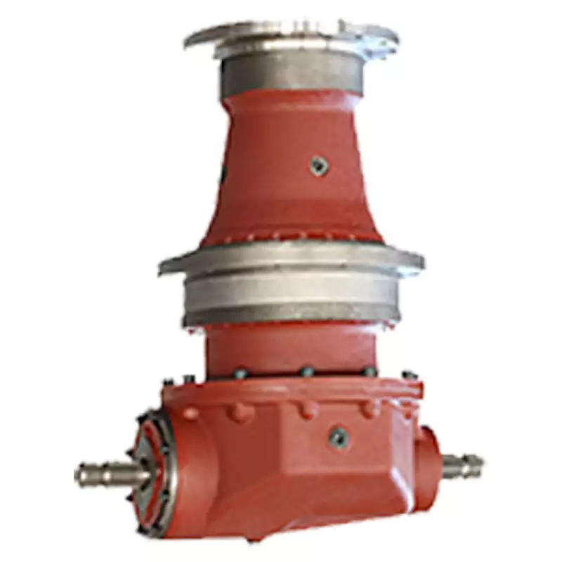
China Hot selling Agricultural Custom Made Small Worm Gear Motor Plainetary Gearbox Car Transmission Speed Reducer Speed Increasing Gear Box for Farm Use Machine near me factory
Item Description
Excellent powder metallurgy elements metallic sintered areas
We could provide different powder metallurgy elements such as iron dependent and copper primarily based with leading top quality and least expensive value, you should only send the drawing or sample to us, we will according to customer’s prerequisite to make it. if you are intrigued in our merchandise, remember to do not wait to make contact with us, we would like to offer you the prime quality and best service for you. thank you!
How do We Operate with Our Customers
one. For a design skilled or a massive organization with your own engineering crew: we prefer to receive a totally RFQ pack from you which includes drawing, 3D model, amount, photos
two. For a start-up organization proprietor or inexperienced hand for engineering: just ship an notion that you want to attempt, you never even need to know what casting is
3. Our revenue will reply you inside 24 hrs to validate additional particulars and give the approximated quotation time
four. Our engineering group will assess your inquiry and offer our offer you in following 1~3 operating times.
5. We can prepare a complex communication conference with you and our engineers with each other at any time if required.
The Benefit of Powder Metallurgy Approach
1. Expense efficient
The closing goods can be compacted with powder metallurgy approach ,and no need to have or can shorten the processing of machine .It can preserve substance significantly and reduce the creation value .
two. Sophisticated styles
Powder metallurgy permits to get complicated shapes right from the compacting tooling ,with out any machining operation ,like teeth ,splines ,profiles ,frontal geometries etc.
3. Higher precision
Achievable tolerances in the perpendicular route of compacting are generally IT 8-9 as sintered,improvable up to IT 5-7 soon after sizing .Further machining functions can increase the precision .
four. Self-lubrication
The interconnected porosity of the material can be crammed with oils ,obtaining then a self-lubricating bearing :the oil offers constant lubrication between bearing and shaft ,and the program does not want any added external lubricant .
five. Environmentally friendly technology
The producing procedure of sintered components is licensed as ecological ,because the material squander is quite minimal ,the product is recyclable ,and the energy efficiency is great due to the fact the substance is not molten.
FAQ
Q1: What is the sort of payment?
A: Usually you must prepay fifty% of the complete quantity. The harmony need to be pay off before shipment.
Q2: How to assure the high top quality?
A: one hundred% inspection. We have Carl Zeiss large-precision tests equipment and screening office to make positive every merchandise of dimensions,physical appearance and strain test are excellent.
Q3: How lengthy will you give me the reply?
A: we will speak to you in 12 hours as soon as we can.
Q4. How about your supply time?
A: Typically, it will get 25 to 35 days right after receiving your progress payment. The specific shipping time depends on the products and the quantity of your get. and if the product was non regular, we have to take into account added ten-15days for tooling/mould produced.
Q5. Can you generate in accordance to the samples or drawings?
A: Of course, we can generate by your samples or specialized drawings. We can construct the molds and fixtures.
Q6: How about tooling Cost?
A: Tooling charge only charge after when first order, all foreseeable future orders would not demand again even tooling repair or beneath maintance.
Q7: What is your sample policy?
A: We can supply the sample if we have all set components in inventory, but the customers have to pay out the sample expense and the courier cost.
Q8: How do you make our enterprise lengthy-phrase and excellent connection?
A: 1. We keep very good good quality and aggressive price tag to guarantee our clients benefit
2. We respect each buyer as our buddy and we sincerely do business and make buddies with them, no make a difference in which they appear from.
| Place of origin: | Jangsu,China |
| Type: | Powder metallurgy sintering |
| Spare parts type: | Powder metallurgy parts |
| Machinery Test report: | Provided |
| Material: | Iron,stainless,steel,copper |
| Key selling points: | Quality assurance |
| Mould type: | Tungsten steel |
| Material standard: | MPIF 35,DIN 30910,JIS Z 2550 |
| Application: | Small home appliances,Lockset,Electric tool, automobile, |
| Brand Name: | OEM SERVICE |
| Plating: | Customized |
| After-sales Service: | Online support |
| Processing: | Powder Metallurgr,CNC Machining |
| Powder Metallurgr: | High frequency quenching, oil immersion |
| Quality Control: | 100% inspection |
Types of Miter Gears
The different types of miter gears include Hypoid, Crown, and Spiral. To learn more, read on. In addition, you’ll learn about their differences and similarities. This article will provide an overview of the different types of miter gears. You can also choose the type that fits your needs by using the guide below. After you’ve read it, you’ll know how to use them in your project. You’ll also learn how to pair them up by hand, which is particularly useful if you’re working on a mechanical component.
Bevel gears
Bevel and miter gears are both used to connect two shafts that have different axes. In most cases, these gears are used at right angles. The pitch cone of a bevel gear has the same shape as that of a spur gear, except the tooth profile is slightly tapered and has variable depth. The pinions of a bevel gear are normally straight, but can be curved or skew-shaped. They can also have an offset crown wheel with straight teeth relative to the axis.
In addition to their industrial applications, miter gears are found in agriculture, bottling, printing, and various industrial sectors. They are used in coal mining, oil exploration, and chemical processes. They are an important part of conveyors, elevators, kilns, and more. In fact, miter gears are often used in machine tools, like forklifts and jigsaws.
When considering which gear is right for a certain application, you’ll need to think about the application and the design goals. For example, you’ll want to know the maximum load that the gear can carry. You can use computer simulation programs to determine the exact torque required for a specific application. Miter gears are bevel gears that are geared on a single axis, not two.
To calculate the torque required for a particular application, you’ll need to know the MA of each bevel gear. Fortunately, you can now do so with CZPT. With the help of this software, you can generate 3D models of spiral bevel gears. Once you’ve created your model, you can then machine it. This can make your job much easier! And it’s fun!
In terms of manufacturing, straight bevel gears are the easiest to produce. The earliest method for this type of gear is a planer with an indexing head. Since the development of CNC machining, however, more effective manufacturing methods have been developed. These include CZPT, Revacycle, and Coniflex systems. The CZPT uses the Revacycle system. You can also use a CNC mill to manufacture spiral bevel gears.
Hypoid bevel gears
When it comes to designing hypoid bevel gears for miter and other kinds of gears, there are several important parameters to consider. In order to produce high-quality gearings, the mounting distance between the gear teeth and the pinion must be within a predefined tolerance range. In other words, the mounting distance between the gear teeth and pinion must be 0.05 mm or less.
To make this possible, the hypoid bevel gearset mesh is designed to involve sliding action. The result is a quiet transmission. It also means that higher speeds are possible without increasing noise levels. In comparison, bevel gears tend to be noisy at high speeds. For these reasons, the hypoid gearset is the most efficient way to build miter gears. However, it’s important to keep in mind that hypoid gears are not for every application.
Hypoid bevel gears are analogous to spiral bevels, but they don’t have intersecting axes. Because of this, they can produce larger pinions with smooth engagement. Crown bevel gears, on the other hand, have a 90-degree pitch and parallel teeth. Their geometry and pitch is unique, and they have particular geometrical properties. There are different ways to express pitch. The diametral pitch is the number of teeth, while circumferential measurement is called the circumference.
The face-milling method is another technique used for the manufacture of hypoid and spiral bevel gears. Face-milling allows gears to be ground for high accuracy and surface finish. It also allows for the elimination of heat treatment and facilitates the creation of predesigned ease-off topographies. Face-milling increases mechanical resistance by as much as 20%. It also reduces noise levels.
The ANSI/AGMA/ISO standards for geometric dimensioning differ from the best practices for manufacturing hypoid and bevel gears. The violation of common datum surfaces leads to a number of geometrical dimensioning issues. Moreover, hypoid gears need to be designed to incorporate the base pitches of the mating pinion and the hypoid bevel gear. This is not possible without knowing the base pitch of the gear and the mating pinion.
Crown bevel gears
When choosing crown bevels for a miter gear, you will need to consider a number of factors. Specifically, you will need to know the ratio of the tooth load to the bevel gear pitch radius. This will help you choose a bevel gear that possesses the right amount of excitation and load capacity. Crown bevels are also known as helical gears, which are a combination of two bevel gear types.
These bevel gears differ from spiral bevels because the bevels are not intersected. This gives you the flexibility of using a larger pinion and smoother engagement. Crown bevel gears are also named for their different tooth portions: the toe, or the part of the gear closest to the bore, and the heel, or the outermost diameter. The tooth height is smaller at the toe than it is at the heel, but the height of the gear is the same at both places.
Crown bevel gears are cylindrical, with teeth that are angled at an angle. They have a 1:1 gear ratio and are used for miter gears and spur gears. Crown bevel gears have a tooth profile that is the same as spur gears but is slightly narrower at the tip, giving them superior quietness. Crown bevel gears for miter gears can be made with an offset pinion.
There are many other options available when choosing a Crown bevel gear for miter gears. The material used for the gears can vary from plastics to pre-hardened alloys. If you are concerned with the material’s strength, you can choose a pre-hardened alloy with a 32-35 Rc hardness. This alloy also has the advantage of being more durable than plastic. In addition to being stronger, crown bevel gears are also easier to lubricate.
Crown bevel gears for miter gears are similar to spiral bevels. However, they have a hyperbolic, not conical, pitch surface. The pinion is often offset above or below the center of the gear, which allows for a larger diameter. Crown bevel gears for miter gears are typically larger than hypoid gears. The hypoid gear is commonly used in automobile rear axles. They are useful when the angle of rotation is 90 degrees. And they can be used for 1:1 ratios.
Spiral miter gears
Spiral bevel gears are produced by machining the face surface of the teeth. The process follows the Hertz theory of elastic contact, where the dislocations are equivalent to small significant dimensions of the contact area and the relative radii of curvature. This method assumes that the surfaces are parallel and that the strains are small. Moreover, it can reduce noise. This makes spiral bevel gears an ideal choice for high-speed applications.
The precision machining of CZPT spiral miter gears reduces backlash. They feature adjustable locking nuts that can precisely adjust the spacing between the gear teeth. The result is reduced backlash and maximum drive life. In addition, these gears are flexible enough to accommodate design changes late in the production process, reducing risk for OEMs and increasing efficiency and productivity. The advantages of spiral miter gears are outlined below.
Spiral bevel gears also have many advantages. The most obvious of these advantages is that they have large-diameter shafts. The larger shaft size allows for a larger diameter gear, but this means a larger gear housing. In turn, this reduces ground clearance, interior space, and weight. It also makes the drive axle gear larger, which reduces ground clearance and interior space. Spiral bevel gears are more efficient than spiral bevel gears, but it may be harder to find the right size for your application.
Another benefit of spiral miter gears is their small size. For the same amount of power, a spiral miter gear is smaller than a straight cut miter gear. Moreover, spiral bevel gears are less likely to bend or pit. They also have higher precision properties. They are suitable for secondary operations. Spiral miter gears are more durable than straight cut ones and can operate at higher speeds.
A key feature of spiral miter gears is their ability to resist wear and tear. Because they are constantly being deformed, they tend to crack in a way that increases their wear and tear. The result is a harder gear with a more contoured grain flow. But it is possible to restore the quality of your gear through proper maintenance. If you have a machine, it would be in your best interest to replace worn parts if they aren’t functioning as they should.
China Custom CZPT AC2 Vvvf Elevator Geared Traction Machine Motor Nv41g-200 with Best Sales
Merchandise Description
Elevator Geared Traction Machine specification:
Elevator Geared Traction Device Photo:
Elevator Geared Traction Machine Firm Info:
Elevator Geared Traction Machine Workshop:
Elevator Geared Traction Device CE Certifications:
Elevator Traction Equipment Exhibition In Germany,Russia,Georgia:
The Rewards of Utilizing a Gear Motor
A gear motor functions on the principle of conservation of angular momentum. As the smaller gear addresses much more RPM and the larger equipment makes far more torque, the ratio among the two is increased than one particular. Similarly, a several equipment motor follows the basic principle of vitality conservation, with the course of rotation always reverse to the a single that is adjacent to it. It’s straightforward to realize the principle powering gear motors and the different sorts available. Go through on to discover about the various varieties of gears and their applications.
Electric powered motor
The decision of an electrical motor for equipment motor is mostly dependent on the application. There are various motor and gearhead mixtures obtainable, and some are a lot more efficient than other folks. Nevertheless, it is vital to recognize the application needs and decide on a motor that satisfies these demands. In this post, we’ll analyze some of the rewards of using a gear motor. The execs and negatives of every single type are briefly mentioned. You can acquire new equipment motors at aggressive costs, but they are not the most trustworthy or resilient selection for your software.
To establish which motor is greatest for your application, you’ll require to take into account the load and velocity specifications. A gear motor’s efficiency (e) can be calculated by getting the enter and output values and calculating their relation. On the graph beneath, the input (T) and output (P) values are represented as dashed strains. The enter (I) price is represented as the torque utilized to the motor shaft. The output (P) is the amount of mechanical strength converted. A DC gear motor is 70% efficient at 3.75 lb-in / 2,100 rpm.
In addition to the worm gear motor, you can also select a compact DC worm equipment motor with a variable gear ratio from 7.5 to 80. It has a selection of choices and can be customized-produced for your specific application. The 3-period AC equipment motor, on the other hand, operates at a rated electricity of a single hp and torque of 1.143.2 kg-m. The output voltage is typically 220V.
Yet another crucial issue is the output shaft orientation. There are two major orientations for gearmotors: in-line and offset. In-line output shafts are most excellent for applications with high torque and quick reduction ratios. If you want to stay away from backlash, select a right angle output shaft. An offset shaft can result in the output shaft to become excessively very hot. If the output shaft is angled at a specified angle, it could be as well large or too tiny.
Gear reducer
A gear reducer is a particular sort of velocity minimizing motor, typically employed in massive machinery, this sort of as compressors. These reducers have no cooling admirer and are not created to take care of large hundreds. Diverse functions demand different support aspects. For occasion, a machine that requires regular rapidly accelerations and occasional load spikes wants a gear reducer with a high support factor. A gear reducer which is developed for extended manufacturing shifts must be bigger than a equipment that uses it for quick periods of time.
A gear reducer can lessen the pace of a motor by a element of two. The reduction ratio alterations the rotation pace of the receiving member. This adjust in velocity is usually needed to resolve issues of inertia mismatch. The torque density of a equipment reducer is calculated in newton meters and will count on the motor utilized. The 1st criterion is the configuration of the enter and output shafts. A gear ratio of 2:1, for illustration, implies that the output pace has been lower in fifty percent.
Bevel gear reducers are a excellent option if the input and output shafts are perpendicular. This kind is really sturdy and is perfect for circumstances exactly where the angle between two axes is little. Nonetheless, bevel equipment reducers are pricey and need continual maintenance. They are normally utilized in heavy-responsibility conveyors and farm tools. The appropriate option of equipment reducer for equipment motor is vital for the effectiveness and trustworthiness of the system. To get the ideal gear reducer for your application, chat to a experienced producer nowadays.
Picking a gear reducer for a equipment motor can be tricky. The incorrect 1 can damage an complete machine, so it is critical to know the particulars. You need to know the torque and velocity specifications and decide on a motor with the appropriate ratio. A equipment reducer must also be suitable with the motor it is supposed for. In some cases, a scaled-down motor with a equipment reducer will operate much better than a larger a single.
Motor shaft
Proper alignment of the motor shaft can significantly increase the performance and daily life span of rotating products. The proper alignment of motors and pushed instruments boosts the transfer of energy from the motor to the instrument. Incorrect alignment leads to additional sounds and vibration. It may possibly also direct to untimely failure of couplings and bearings. Misalignment also final results in improved shaft and coupling temperatures. Hence, proper alignment is vital to increase the effectiveness of the driven instrument.
When selecting the right sort of equipment train for your motor, you need to think about its strength effectiveness and the torque it can handle. A helical geared motor is a lot more productive for high output torque purposes. Based on the needed speed and torque, you can pick between an in-line and a parallel helical geared motor. The two kinds of gears have their positive aspects and drawbacks. Spur gears are widespread. They are toothed and run parallel to the motor shaft.
A planetary equipment motor can also have a linear output shaft. A stepping motor need to not function at too higher current to stop demagnetization, which will lead to phase decline or torque fall. Ensure that the motor and gearbox output shafts are guarded from external impacts. If the motor and gearbox are not guarded towards bumps, they could cause thread problems. Make sure that the motor shafts and rotors are safeguarded from external impacts.
When choosing a metal for your gear motor’s motor shaft, you should contemplate the expense of very hot-rolled bar inventory. Its outer levels are a lot more tough to equipment. This kind of substance includes residual stresses and other problems that make it tough to device. For these applications, you should select a high-power steel with hard outer layers. This sort of metal is cheaper, but it also has size issues. It is ideal to examination each and every material 1st to establish which one particular suits your needs.
In addition to minimizing the velocity of your gadget, a geared motor also minimizes the torque generated by your machine. It can be employed with the two AC and DC energy. A large-high quality gear motor is vital for stirring mechanisms and conveyor belts. Nevertheless, you ought to select a geared motor that makes use of high-grade gears and provides optimum effectiveness. There are many types of planetary equipment motors and gears on the marketplace, and it really is critical to decide on the appropriate 1.
First stage gears
The initial stage gears of a equipment motor are the most important parts of the whole device. The motor’s electrical power transmission is 90% effective, but there are several elements that can affect its performance. The gear ratios used should be large sufficient to handle the load, but not also higher that they are restricting the motor’s pace. A equipment motor must also have a wholesome protection issue, and the lubricant have to be adequate to overcome any of these elements.
The transmission torque of the gear modifications with its speed. The transmission torque at the input side of the equipment decreases, transferring a tiny torque to the output facet. The amount of tooth and the pitch circle diameters can be utilised to calculate the torque. The initial phase gears of equipment motors can be classified as spur gears, helical gears, or worm gears. These three varieties of gears have different torque capacities.
The initial phase helical gear is the most important element of a equipment motor. Its function is to transfer rotation from a single gear to the other. Its output is the gearhead. The 2nd stage gears are connected by a carrier. They work in tandem with the initial stage equipment to provide the output of the gearhead. Additionally, the very first stage carrier rotates in the very same course as the input pinion.
Yet another crucial ingredient is the output torque of the gearmotor. When choosing a gearmotor, contemplate the beginning torque, running torque, output speed, overhung and shock hundreds, obligation cycles, and a lot more. It is essential to decide on a gearmotor with the right ratio for the software. By choosing the suitable gearmotor, you will get optimum functionality with small working costs and improve plant productiveness. For more details on first phase gears, examine out our website.
The 1st stage of a gear motor is composed of a established of set and rotating sprockets. The first stage of these gears functions as a travel gear. Its rotational mass is a limiting aspect for torque. The second stage consists of a rotating shaft. This shaft rotates in the path of the torque axis. It is also the limiting drive for the motor’s torque.

