Insulation Resistance: In the circumstance of normal ambient temperature and humidity, the resistance can be up to 20MΩ or more when DC 500v megger is applied between the windings and the frame after rated motor operations.
Insulation Voltage: In the circumstance of normal ambient temperature and humidity, there will be no problem to withstand 1.5kv at 50Hz/60Hz between the windings and the frame for 1 minute after the rated motor operation.
Temperature Rise: The temperature rise should be lower than 80ºC measured by the resistance method when the motor is working.
Insulation Class: Class B(130ºC)
Use Temperature: -10ºC~+40ºC(Non-Freezing)
Use Humidity: ≤80%(place without dew)
Motor Details
*Motor voltage, power and speed will be customized according to your requirement under the allowed circumstance of adoptable dimension. *For the external brush motor, you can replace the brush directly. For internal ones, we need to disassembly the motor first.
Gear reduction ratio
Drawing
Motor:
Motor + Gearbox:
Note:
If this model is not what you want, please freely tell us about your requirement. We will provide you with a suitable motor solution and price soon.
About Our Company
HISTORY: Greensky is a mechanical brand of Greensky Power Co., Ltd. with over 10 years’ mechanical manufacturing experiences. Greensky Power always strictly stands on the principle of Best Customer Satisfaction.
MISSION: Material Inspection, Production Control, Finished Goods Test, Pre-delivery Inspection
QUALITY: “Once and forever” is our goal to serve customers in the world. Once we do business with the customer, we will do business forever.
MARKET:30 different countries, mainly Germany, Austria, Japan, USA and Middle-East.
DELIVERY:100% on-time delivery Guaranteed.
SERVICES:Fast response in English, German, Japanese and Chinese languages.
OEM:Customized orders are welcome at Greensky Power.
Exhibition
Certificates
FAQ
1 Q: What’s your MOQ? A: 1unit is acceptable.
2 Q: What about your warranty for your 1 phase AC gear motor? A: One year.
3 Q: Do you provide OEM service with customer-logo? A: Yes, we could do OEM orders, but we mainly focus on our own brand.
4 Q: How about your payment terms? A: TT, western union and Paypal. 100% payment in advance for orders less $5,000. 30% deposit and balance before delivery for orders over $5,000.
5 Q: How about your packing? A: Carton, Plywood case and foam inside. If you need more, we can pack all goods with pallet
6 Q: What information should be given, if I buy 1 phase AC gear motor from you? A: Rated power, gearbox ratio, input speed, mounting position. More details, better!
7 Q: How do you deliver the 1 phase ac gear motor? A: We will compare and choose the most suitable ways of delivery by sea, air or express courier.
We hope you will enjoy cooperating with us.
Model
Voltage
Power
No-load data
Load data
Brush life
Motor weight
Speed
Current
Speed
Torque
Current
V
W
r/min
A
r/min
mN.m
A
H
kg
GS2D15-12
12
15
3400
0.8
3000
47
2.1
2000
0.8
GS2D15-24
24
15
3350
0.4
3000
47
1.1
2000
0.8
###
Gear ratio
3
3.6
5
6
7.5
9
10
12.5
15
18
20
25
30
36
40
50
60
75
90
100
120
150
180
200
Speed r/min
999
833
600
500
400
333
300
240
200
166
150
120
100
83
75
60
50
40
33
30
25
20
16.5
15
Torque N.m
0.11
0.14
0.19
0.23
0.29
0.34
0.38
0.48
0.57
0.69
0.76
0.86
1.03
1.23
1.37
1.71
1.85
2.31
2.78
3
3
3
3
3
The Basics of a Planetary Motor
A Planetary Motor is a type of gearmotor that uses multiple planetary gears to deliver torque. This system minimizes the chances of failure of individual gears and increases output capacity. Compared to the planetary motor, the spur gear motor is less complex and less expensive. However, a spur gear motor is generally more suitable for applications requiring low torque. This is because each gear is responsible for the entire load, limiting its torque.
Self-centering planetary gears
This self-centering mechanism for a planetary motor is based on a helical arrangement. The helical structure involves a sun-planet, with its crown and slope modified. The gears are mounted on a ring and share the load evenly. The helical arrangement can be either self-centering or self-resonant. This method is suited for both applications. A helical planetary gear transmission is illustrated in FIG. 1. A helical configuration includes an output shaft 18 and a sun gear 18. The drive shaft extends through an opening in the cover to engage drive pins on the planet carriers. The drive shaft of the planetary gears can be fixed to the helical arrangement or can be removable. The transmission system is symmetrical, allowing the output shaft of the planetary motor to rotate radially in response to the forces acting on the planet gears. A flexible pin can improve load sharing. This modification may decrease the face load distribution, but increases the (K_Hbeta) parameter. This effect affects the gear rating and life. It is important to understand the effects of flexible pins. It is worth noting that there are several other disadvantages of flexible pins in helical PGSs. The benefits of flexible pins are discussed below. Using self-centering planetary gears for a helical planetary motor is essential for symmetrical force distribution. These gears ensure the symmetry of force distribution. They can also be used for self-centering applications. Self-centering planetary gears also guarantee the proper force distribution. They are used to drive a planetary motor. The gearhead is made of a ring gear, and the output shaft is supported by two ball bearings. Self-centering planetary gears can handle a high torque input, and can be suited for many applications. To solve for a planetary gear mechanism, you need to find its pitch curve. The first step is to find the radius of the internal gear ring. A noncircular planetary gear mechanism should be able to satisfy constraints that can be complex and nonlinear. Using a computer, you can solve for these constraints by analyzing the profile of the planetary wheel’s tooth curve.
High torque
Compared to the conventional planetary motors, high-torque planetary motors have a higher output torque and better transmission efficiency. The high-torque planetary motors are designed to withstand large loads and are used in many types of applications, such as medical equipment and miniature consumer electronics. Their compact design makes them suitable for small space-saving applications. In addition, these motors are designed for high-speed operation. They come with a variety of shaft configurations and have a wide range of price-performance ratios. The FAULHABER planetary gearboxes are made of plastic, resulting in a good price-performance ratio. In addition, plastic input stage gears are used in applications requiring high torques, and steel input stage gears are available for higher speeds. For difficult operating conditions, modified lubrication is available. Various planetary gear motors are available in different sizes and power levels. Generally, planetary gear motors are made of steel, brass, or plastic, though some use plastic for their gears. Steel-cut gears are the most durable, and are ideal for applications that require a high amount of torque. Similarly, nickel-steel gears are more lubricated and can withstand a high amount of wear. The output torque of a high-torque planetary gearbox depends on its rated input speed. Industrial-grade high-torque planetary gearboxes are capable of up to 18000 RPM. Their output torque is not higher than 2000 nm. They are also used in machines where a planet is decelerating. Their working temperature ranges between 25 and 100 degrees Celsius. For best results, it is best to choose the right size for the application. A high-torque planetary gearbox is the most suitable type of high-torque planetary motor. It is important to determine the deceleration ratio before buying one. If there is no product catalog that matches your servo motor, consider buying a close-fitting high-torque planetary gearbox. There are also high-torque planetary gearboxes available for custom-made applications.
High efficiency
A planetary gearbox is a type of mechanical device that is used for high-torque transmission. This gearbox is made of multiple pairs of gears. Large gears on the output shaft mesh with small gears on the input shaft. The ratio between the big and small gear teeth determines the transmittable torque. High-efficiency planetary gearheads are available for linear motion, axial loads, and sterilizable applications. The AG2400 high-end gear unit series is ideally matched to Beckhoff’s extensive line of servomotors and gearboxes. Its single-stage and multi-stage transmission ratios are highly flexible and can be matched to different robot types. Its modified lubrication helps it operate in difficult operating conditions. These high-performance gear units are available in a wide range of sizes. A planetary gear motor can be made of steel, nickel-steel, or brass. In addition to steel, some models use plastic. The planetary gears share work between multiple gears, making it easy to transfer high amounts of power without putting a lot of stress on the gears. The gears in a planetary gear motor are held together by a movable arm. High-efficiency planetary gear motors are more efficient than traditional gearmotors. While a planetary gear motor can generate torque, it is more efficient and cheaper to produce. The planetary gear system is designed with all gears operating in synchrony, minimizing the chance of a single gear failure. The efficiency of a planetary gearmotor makes it a popular choice for high-torque applications. This type of motor is suitable for many applications, and is less expensive than a standard geared motor. The planetary gearbox is a combination of a planetary type gearbox and a DC motor. The planetary gearbox is compact, versatile, and efficient, and can be used in a wide range of industrial environments. The planetary gearbox with an HN210 DC motor is used in a 22mm OD, PPH, and ph configuration with voltage operating between 6V and 24V. It is available in many configurations and can be custom-made to meet your application requirements.
High cost
In general, planetary gearmotors are more expensive than other configurations of gearmotors. This is due to the complexity of their design, which involves the use of a central sun gear and a set of planetary gears which mesh with each other. The entire assembly is enclosed in a larger internal tooth gear. However, planetary motors are more effective for higher load requirements. The cost of planetary motors varies depending on the number of gears and the number of planetary gears in the system. If you want to build a planetary gearbox, you can purchase a gearbox for the motor. These gearboxes are often available with several ratios, and you can use any one to create a custom ratio. The cost of a gearbox depends on how much power you want to move with the gearbox, and how much gear ratio you need. You can even contact your local FRC team to purchase a gearbox for the motor. Gearboxes play a major role in determining the efficiency of a planetary gearmotor. The output shafts used for this type of motor are usually made of steel or nickel-steel, while those used in planetary gearboxes are made from brass or plastic. The former is the most durable and is best for applications that require high torque. The latter, however, is more absorbent and is better at holding lubricant. Using a planetary gearbox will allow you to reduce the input power required for the stepper motor. However, this is not without its downsides. A planetary gearbox can also be replaced with a spare part. A planetary gearbox is inexpensive, and its spare parts are inexpensive. A planetary gearbox has low cost compared to a planetary motor. Its advantages make it more desirable in certain applications. Another advantage of a planetary gear unit is the ability to handle ultra-low speeds. Using a planetary gearbox allows stepper motors to avoid resonance zones, which can cause them to crawl. In addition, the planetary gear unit allows for safe and efficient cleaning. So, whether you’re considering a planetary gear unit for a particular application, these gear units can help you get exactly what you need.
NMRVREDUCTION WORM GEARBOX The NMRV 050 motor gearbox is composed of a single-phase NRV 050 worm gearbox coupled to an IEC asynchronous motor. Maximum generate electrical power – 1.5 kW. The torque on the output shaft is 17-89 N * m. The equipment motor is available in 2 mounting versions (legs / flange). Areas components: Situation – aluminum, flanges – aluminum, worm – steel, worm wheel crown – bronze. Type of lubricant: synthetic ISO VG 320. Bodyweight: 3.5 kg.
Sort designation plan
NMRV – 050 – 30 – 93.3 – 0.75 – B1
NMRV – worm equipment motor
050 – size (centre distance, mm)
thirty – gear ratio
93.3 – output shaft rotation velocity, rpm
.75 – electric motor energy, kW
B1 – mounting placement
NMRV 050 gearbox performance
n1 – rotational speed el. motor
n2 – revolutions on the output shaft
T2M – torque on the output shaft
P is the highest allowable motor energy
RD – efficiency
GEARBOX Feature
General and mounting proportions NMRV 050
NMRV050 gear motor has a wide assortment of equipment ratios. Gear ratios: 5, 7.5, ten, 15, 20, twenty five, 30, 40, fifty, sixty, eighty, one hundred .
Output flange to NMRV 050 gearbox
Geared NMRV050 can be equipped with unilateral or bilateral output shaft. The gearbox comes common with a hollow output shaft
A torque arm is an added alternative to the gearbox.
RV30-90:synthetic oil, RV110-150:GN460-W mineral oil
Bearings
C&U
###
How to Replace the Drive Shaft
Several different functions in a vehicle are critical to its functioning, but the driveshaft is probably the part that needs to be understood the most. A damaged or damaged driveshaft can damage many other auto parts. This article will explain how this component works and some of the signs that it may need repair. This article is for the average person who wants to fix their car on their own but may not be familiar with mechanical repairs or even driveshaft mechanics. You can click the link below for more information.
Repair damaged driveshafts
If you own a car, you should know that the driveshaft is an integral part of the vehicle’s driveline. They ensure efficient transmission of power from the engine to the wheels and drive. However, if your driveshaft is damaged or cracked, your vehicle will not function properly. To keep your car safe and running at peak efficiency, you should have it repaired as soon as possible. Here are some simple steps to replace the drive shaft. First, diagnose the cause of the drive shaft damage. If your car is making unusual noises, the driveshaft may be damaged. This is because worn bushings and bearings support the drive shaft. Therefore, the rotation of the drive shaft is affected. The noise will be squeaks, dings or rattles. Once the problem has been diagnosed, it is time to repair the damaged drive shaft. Professionals can repair your driveshaft at relatively low cost. Costs vary depending on the type of drive shaft and its condition. Axle repairs can range from $300 to $1,000. Labor is usually only around $200. A simple repair can cost between $150 and $1700. You’ll save hundreds of dollars if you’re able to fix the problem yourself. You may need to spend a few more hours educating yourself about the problem before handing it over to a professional for proper diagnosis and repair. The cost of repairing a damaged driveshaft varies by model and manufacturer. It can cost as much as $2,000 depending on parts and labor. While labor costs can vary, parts and labor are typically around $70. On average, a damaged driveshaft repair costs between $400 and $600. However, these parts can be more expensive than that. If you don’t want to spend money on unnecessarily expensive repairs, you may need to pay a little more.
Learn how drive shafts work
While a car engine may be one of the most complex components in your vehicle, the driveshaft has an equally important job. The driveshaft transmits the power of the engine to the wheels, turning the wheels and making the vehicle move. Driveshaft torque refers to the force associated with rotational motion. Drive shafts must be able to withstand extreme conditions or they may break. Driveshafts are not designed to bend, so understanding how they work is critical to the proper functioning of the vehicle. The drive shaft includes many components. The CV connector is one of them. This is the last stop before the wheels spin. CV joints are also known as “doughnut” joints. The CV joint helps balance the load on the driveshaft, the final stop between the engine and the final drive assembly. Finally, the axle is a single rotating shaft that transmits power from the final drive assembly to the wheels. Different types of drive shafts have different numbers of joints. They transmit torque from the engine to the wheels and must accommodate differences in length and angle. The drive shaft of a front-wheel drive vehicle usually includes a connecting shaft, an inner constant velocity joint and an outer fixed joint. They also have anti-lock system rings and torsional dampers to help them run smoothly. This guide will help you understand the basics of driveshafts and keep your car in good shape. The CV joint is the heart of the driveshaft, it enables the wheels of the car to move at a constant speed. The connector also helps transmit power efficiently. You can learn more about CV joint driveshafts by looking at the top 3 driveshaft questions The U-joint on the intermediate shaft may be worn or damaged. Small deviations in these joints can cause slight vibrations and wobble. Over time, these vibrations can wear out drivetrain components, including U-joints and differential seals. Additional wear on the center support bearing is also expected. If your driveshaft is leaking oil, the next step is to check your transmission. The drive shaft is an important part of the car. They transmit power from the engine to the transmission. They also connect the axles and CV joints. When these components are in good condition, they transmit power to the wheels. If you find them loose or stuck, it can cause the vehicle to bounce. To ensure proper torque transfer, your car needs to stay on the road. While rough roads are normal, bumps and bumps are common.
Common signs of damaged driveshafts
If your vehicle vibrates heavily underneath, you may be dealing with a faulty propshaft. This issue limits your overall control of the vehicle and cannot be ignored. If you hear this noise frequently, the problem may be the cause and should be diagnosed as soon as possible. Here are some common symptoms of a damaged driveshaft. If you experience this noise while driving, you should have your vehicle inspected by a mechanic. A clanging sound can also be one of the signs of a damaged driveshaft. A ding may be a sign of a faulty U-joint or center bearing. This can also be a symptom of worn center bearings. To keep your vehicle safe and functioning properly, it is best to have your driveshaft inspected by a certified mechanic. This can prevent serious damage to your car. A worn drive shaft can cause difficulty turning, which can be a major safety issue. Fortunately, there are many ways to tell if your driveshaft needs service. The first thing you can do is check the u-joint itself. If it moves too much or too little in any direction, it probably means your driveshaft is faulty. Also, rust on the bearing cap seals may indicate a faulty drive shaft. The next time your car rattles, it might be time for a mechanic to check it out. Whether your vehicle has a manual or automatic transmission, the driveshaft plays an important role in your vehicle’s performance. When one or both driveshafts fail, it can make the vehicle unsafe or impossible to drive. Therefore, you should have your car inspected by a mechanic as soon as possible to prevent further problems. Your vehicle should also be regularly lubricated with grease and chain to prevent corrosion. This will prevent grease from escaping and causing dirt and grease to build up. Another common sign is a dirty driveshaft. Make sure your phone is free of debris and in good condition. Finally, make sure the driveshaft chain and cover are in place. In most cases, if you notice any of these common symptoms, your vehicle’s driveshaft should be replaced. Other signs of a damaged driveshaft include uneven wheel rotation, difficulty turning the car, and increased drag when trying to turn. A worn U-joint also inhibits the ability of the steering wheel to turn, making it more difficult to turn. Another sign of a faulty driveshaft is the shuddering noise the car makes when accelerating. Vehicles with damaged driveshafts should be inspected as soon as possible to avoid costly repairs.
HangZhou CZPT Tech.Equipment Co.,Ltd was founded in 2003. It is positioned at HangZhou County, HangZhou Town, closed to 204 Nationwide Road.Our main products: 1. all kinds of drive shaft 2.all sorts of gera box 3. Farm equipment: IMT500 inorganic fertilizer spreader, HMT05S organic fertilizer spreader, 3M rotovator , 3M wet-paddy area rotary, King 185 deep cultviating machine and so on. 4.The equipment components: many sorts of Equipment, Shaft, Flang, ,Equipment box, Laser parts, Stamping areas and so on.
seven. FAQ
one. Q: Are your merchandise cast or cast?
A: All of our products are forged.
2. Q: What’s your MOQ? A: 20 PCS for every single kind. We accept the sample purchase. three. Q: What’s the horse electrical power of the pto shaft are obtainable? A: We supply a complete range of pto shaft, ranging from 16HP-200HP. 4. Q: How several splined specification do you have ? A: We generate 1 1/8″-Z6, 1 3/8″-Z6, 1 3/4″-Z6, 1 3/8″- Z21, 1 3/4″-Z20, 8X42X48X8 and 8X32X38X6 splines. five. Q: How about the guarantee? A: We guarantee 1 calendar year warranty. With high quality problems, we will deliver you the new merchandise for free in next cargo. six. Q: What’s your payment phrases? A: T/T, L/C, D/A, D/P…. seven. Q: What is the shipping time? A: 40 times after acquiring your advanced deposit.
small gearbox
###
MODEL
INPUT DATA
OUTPUT DATA
Ratio
Maximum Rpm
KW
HP-CV
N.M
N.M
R.P.M
AC78845A/B
1:1.93
800
30
40
358
185
1544
RC
1:1.93
800
30
40
358
185
1544
RC5/BB60X
1:1.69
800
37
50
440
260
1352
AC78846A/B
1:1.93
540
55
75
972
504
1042
612619
1:1.93
540
74
100
1308
678
1042
612666
1:1.46
540
74
100
1308
896
680
BB84X
1:1.26
540
67
90
1184
940
680
RC81-000-01
1:1.923
540
74
100
1308
680
1038
RC81-000-02
1:1.46
540
74
100
1308
896
788
75356-192
1:1.92
540
97
130
1715
893
1037
75356-146
1:1.46
540
97
130
1715
1175
788
74823-19
1:1.87
540
97
130
1715
918
1009
74823-14
1:1.39
540
97
130
1715
1235
750
GT40U.B
3:1
540
44
60
778
2334
180
SF-100
1:1
540
15
20
265
265
540
MCT-100A1
7.5:1
540
29.5
40
521
3912
72
MCT-100A2
22.5:1
540
29.5
40
521
11738
24
DCR1-0000
2.4:1
540
37
50
654
1570
225
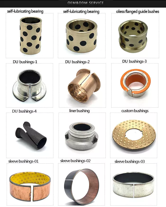
Bushing Application, Type and Compression Capability
Bushings are cylindrical bushings used in machinery. It prevents wear of moving parts and is often used as an enclosure. Bushings are also known as plain bearings or sleeve bearings. You may be wondering what these parts do and how they work, but this article aims to answer all your questions. We’ll cover bushing applications, types and compression capabilities so you can choose the right one for your needs.
application
A bushing is a mechanical component that plays an important role in many different fields. In addition to being very practical, it helps reduce noise, vibration, wear and provides anti-corrosion properties. These properties help mechanical equipment in various ways, including making it easier to maintain and reducing its overall structure. The functionality of an enclosure depends on its purpose and environment. This article will discuss some of the most common applications of casing. For example, in an aircraft, the bushing assembly 16 may be used for the bulkhead isolator 40 . The bushing assembly 16 provides the interfaces and paths required for current flow. In this manner, the sleeve assembly provides a secure, reliable connection between two objects with different electrical charges. They also prevent sparking by increasing the electrical conductivity of the component and reducing its resistivity, thereby minimizing the chance of spark formation. Another common application for bushings is as a support shaft. Unlike bearings, bushings operate by sliding between two moving surfaces. As a result, they reduce friction and handling stress, reducing overall maintenance costs. Typically, the bushing is made of brass or bronze. The benefits of bushings are similar to those of bearings. They help extend the life of rotating machines by reducing frictional energy loss and wear. In addition to identifying growth opportunities and minimizing risks, the Bushing Anti-Vibration Mounts Market report provides insights into the dynamics of the industry and its key players. The report covers global market size, applications, growth prospects, challenges and regional forecasts. The detailed section on Bushing Anti-Vibration Mounts industry provides insights on demand and supply along with competitive analysis at regional and country level.
type
There are several types of bushings. Among them, the SF6 insulating sleeve has the simplest structure and is based on composite hollow insulators. It also has several metal shielding cylinders for regulating the electric field within the enclosure and another for grounding the metal shield. In addition to being lightweight, this sleeve is also very durable, but the diameter of its shield electrode is very large, which means special installation and handling procedures are required. Linear bushings are usually pressed into the bore of the shaft and provide support as the shaft moves in/out. Non-press-fit bushings are held in place by snap rings or pins. For certain applications, engineers often choose bushings over bearings and vice versa. That’s why. Below are some common bushing types. If you need to buy, make sure you know how to tell them apart. OIP bushings are used for oil-filled cable boxes, and oil-to-oil bushings are used for EHV power transformers. The main components of the OIP enclosure are shown in Figure 7a. If you are considering this type of bushing for your specific application, you need to make sure you understand your specific requirements. You can also consult your local engineering department for more information. All types of bushings should be tested for IR and capacitance. The test tap should be securely attached to the bushing flange. If damaged bushings are found, replace them immediately. Be sure to keep complete records of the enclosure for routine maintenance and any IR testing. Also, be sure to pay attention to tan d and thermal vision measurements.
Compressive ability
There are several things to consider when choosing an enclosure. First, the material. There are two main types of bushings: those made of filled Teflon and those made of polyester resin. The former has the highest compressive strength, while the latter has a lower compressive capacity. If you need small amounts, glass-filled nylon bushings are the most common and best option. Glass-filled nylon is an economical material with a compressive strength of 36,000 lbs. Second, the material used for the enclosure must be able to withstand the load. For example, bronze bushings can cause metal shavings to fall into the papermaking process. CG materials can withstand very high levels of moisture, which can damage bushings that require lubrication. Additionally, these materials can operate for extended periods of time without lubrication. This is particularly advantageous in the paper industry, since the casing operates in a humid environment. In addition to the material and its composition, other characteristics of the enclosure must also be considered, including its operating temperature. Although frictional heat from moving loads and the temperature of the bushing itself can affect the performance of the bushing, these factors determine its service life. For high temperature applications, the PV of the enclosure should be kept low. On the other hand, plastic bushings are generally less heat resistant than metal bushings. In addition, plastic sleeves have a high rate of thermal expansion. To avoid this, size control is also important. Low pressure bushings have different requirements. An 800 MVA installation requires a low voltage bushing rated at 14 000 A. The palm assembly of the transformer also features a large central copper cylinder for electrical current. The bushing must withstand this amount of current and must maintain an even distribution of current in the transformer tank. If there is a leak, the bushing must be able to resist the leak so as not to damage the transformer.
cost
The cost of new control arm bushings varies widely. Some parts are cheaper than others, and a new part is only $200. However, if you replace the four control bushings in your car, the cost can exceed $1,200. The cost breakdown for each section is listed below. If you plan to replace all four, the cost of each bushing may range from $200 to $500. The control arm bushing bears the brunt of the forces generated by the tire and is parallel to the direction of the force. However, over time, these components wear out and need to be replaced. Replacing one control arm bushing costs between $300 and $1,200. However, the cost of replacing each arm bushing depends on your car model and driving habits. The control arm bushings should last about 100,000 miles before needing replacement. The repair process for control arm bushings is time consuming and expensive. Also, they may need to remove the heat shield or bracket. In either case, the procedure is simple. Stabilizer bar brackets are usually attached with one or two mounting bolts. They can also be secured with nuts or threaded holes. All you need is a wrench to remove them. The control arm bushings are made of two metal cylinders and a thick rubber bushing. These parts can deteriorate from potholes, off-roading or accidents. Because they are made of rubber, the parts are more expensive than new. Buying used ones can save you money because you don’t need to install them yourself. However, if you do plan on fixing a luxury car yourself, be sure to find one that has a warranty and warranty.
maintain
To prevent your vehicle from overheating and leaking oil, a properly functioning bushing must be used. If the oil level is too low, you will need to check the mounting bolts to make sure they are properly tightened. Check gasket to ensure proper compression is applied, replace bushing if necessary. You should notify your vehicle manufacturer if your vehicle is immersed in oil. Whenever an oil leak occurs, it is very important to replace the oil-filled bushing. Another important aspect of bushing maintenance is the detection and correction of partial discharges. Partial discharge is caused by current entering the bushing. Partial discharge can cause tree-like structures, cracks and carbonization in the discharge channel, which can eventually damage the casing. Early detection of these processes is critical to ensuring that your vehicle’s bushings are properly maintained. Identifying and repairing partial discharges is critical to ensuring optimal operation, regardless of the type of pump or motor. To diagnose casing condition, perform several tests. You can use tan d measurement, which is a powerful tool for detecting the ingress of water and moisture. You can also use power factor measurements to detect localized defects and aging effects. You can also check the oil level by performing an infrared check. After completing these tests, you will be able to determine if there is enough oil in the casing. If the oil level in the transformer is too low, water and air may leak into the transformer. To avoid this problem, be sure to check the MOG and transformer oil levels. If the silicone is pink, replace it. You should also check the function of the oil pump, fan and control circuits annually. Check the physical condition of the pump and fan and whether they need to be replaced. Clean the transformer bushing with a soft cotton cloth and inspect for cracks.
Pneumatic Air Motor/ TMH8 Piston Air Motor For Atalas’ CM351 Crawler Drill Product Introduction
TMH8 Piston air motor is operated on the basis of the following principles. After
entering into the air distribution system (valve core and valve sleeve), the compressed air is accordingly delivered into cylinders, expanding to push the piston reciprocating; the pistons then drive the shaft and crank journal reciprocating and finally output driving power.
Features
1. High starting torque enables starting with load, fast and reliable to start and stall; 2. Concise structure, compact in size and light in weight, easy to operate and convenient to maintain; 3. Stable under inflammable, explosive, outdoor, wet, damp and other extremely conditions; 4. The equipped anti-load function enables the motor to rotate at low speed when overload, and regain high speed when overload relived. 5. Change air-inlet and air-outlet direction to rotate and counter-rotate the motor in short time, with no impact and even not need to relieve the load; 6. Stepless in speed, adjusting air volume to change rotate speed and power; 7. Widely used in minings, oilfields, constructions, smelting, paper making, pharmacy, chemicals, etc,. This motor is ideal mated driving machine for large-scale drilling machines.
8. ISO, API, CCS Approved. Parameters
Sales’ Network
Company’s Show
Any questions, welcome.
How to Select a Gear Motor
A gearmotor is an electrical machine that transfers energy from one place to another. There are many types of gearmotors. This article will discuss the types of gearmotors, including Angular geared motors, Planetary gearboxes, Hydraulic gear motors, and Croise motors. In addition to its uses, gearmotors have many different characteristics. In addition, each type has distinct advantages and disadvantages. Listed below are a few tips on selecting a gearmotor.
Angular geared motors
Angular geared motors are the optimum drive element for applications where torques, forces, and motions need to be transferred at an angle. Compared to other types of geared motors, these have few moving parts, a compact design, and a long life. Angular geared motors are also highly efficient in travel drive applications. In addition to their durability, they have a low maintenance requirement and are highly corrosion-resistant. Helical worm geared motors are a low-cost solution for drives that employ angular geared motors. They combine a worm gear stage and helical input stage to offer higher efficiency than pure worm geared motors. This drive solution is highly reliable and noise-free. Angular geared motors are often used in applications where noise is an issue, and helical worm geared motors are particularly quiet. The gear ratio of an angular geared motor depends on the ratio between its input and output shaft. A high-quality helical geared motor has a relatively low mechanical noise level, and can be installed in almost any space. The torque of a helical geared motor can be measured by using frequency measurement equipment. The energy efficiency of angular geared motors is one of the most important factors when choosing a motor. Its symmetrical arrangement also allows it to operate in low-speed environments. When selecting the right angular geared motor, it is important to keep in mind that increased torque will lead to poor output performance. Once a gear motor reaches its stall torque, it will no longer function properly. This makes it important to consult a performance curve to choose the appropriate motor. Most DC motor manufacturers are more than happy to provide these to customers upon request. Angular geared motors are more expensive than conventional worm gear motors.
Planetary gearboxes
Planetary gearboxes are used in industrial machinery to generate higher torque and power density. There are three main types of planetary gearboxes: double stage, triple stage, and multistage. The central sun gear transfers torque to a group of planetary gears, while the outer ring and spindle provide drive to the motor. The design of planetary gearboxes delivers up to 97% of the power input. The compact size of planetary gears results in excellent heat dissipation. In some applications, lubrication is necessary to improve durability. Nevertheless, if you are looking for high speed transmission, you should consider the additional features, such as low noise, corrosion resistance, and construction. Some constructors are better than others. Some are quick to respond, while others are unable to ship their products in a timely fashion. The main benefit of a planetary gearbox is its compact design. Its lightweight design makes it easy to install, and the efficiency of planetary gearboxes is up to 0.98%. Another benefit of planetary gearboxes is their high torque capacity. These gearboxes are also able to work in applications with limited space. Most modern automatic transmissions in the automotive industry use planetary gears. In addition to being low in cost, planetary gearboxes are a great choice for many applications. Neugart offers both compact and right angle versions. The right angle design offers a high power-to-weight ratio, making it ideal for applications where torque is needed to be transmitted in reverse mode. So if you’re looking for an efficient way to move heavy machinery around, planetary gearboxes can be a great choice. Another advantage of planetary gearboxes is their ability to be easily and rapidly changed from one application to another. Since planetary gears are designed to be flexible, you don’t have to buy new ones if you need to change gear ratios. You can also use planetary gears in different industries and save on safety stock by sharing common parts. These gears are able to withstand high shock loads and demanding conditions.
Hydraulic gear motors
Hydraulic gear motors are driven by oil that is pumped into a gear box and causes the gears to rotate. This method of energy production is quiet and inexpensive. The main drawbacks of hydraulic gear motors are that they are noisy and inefficient at low speeds. The other two types of hydraulic motors are piston and vane-type hydraulic motors. The following are some common benefits of hydraulic gear motors. A hydraulic gear motor is composed of two gears – a driven gear and an idler. The driven gear is attached to the output shaft via a key. High-pressure oil flows into the housing between the gear tips and the motor housing, and the oil then exits through an outlet port. Unlike a conventional gear motor, the gears mesh to prevent the oil from flowing backward. As a result, they are an excellent choice for agricultural and industrial applications. The most common hydraulic gear motors feature a gerotor and a drive gear. These gears mesh with a larger gear to produce rotation. There are also three basic variations of gear motors: roller-gerotor, gerotor, and differential. The latter produces higher torque and less friction than the previous two. These differences make it difficult to choose which type is the best for your needs. A high-performance gear motor will last longer than an ordinary one. Radial piston hydraulic motors operate in the opposite direction to the reciprocating shaft of an electric gearmotor. They have nine pistons arranged around a common center line. Fluid pressure causes the pistons to reciprocate, and when they are stationary, the pistons push the fluid out and move back in. Because of the high pressure created by the fluid, they can rotate at speeds up to 25,000RPM. In addition, hydraulic gear motors are highly efficient, allowing them to be used in a wide range of industrial and commercial applications. Hydraulic gear motors complement hydraulic pumps and motors. They are also available in reversible models. To choose the right hydraulic motor for your project, take time to gather all the necessary information about the installation process. Some types require specialized expertise or complicated installation. Also, there are some differences between closed and open-loop hydraulic motors. Make sure to discuss the options with a professional before you make a decision.
Croise motors
There are many advantages to choosing a Croise gear motor. It is highly compact, with less weight and space than standard motors. Its right-angle shaft and worm gear provide smooth, quiet operation. A silent-type brake ensures no metallic sound during operation. It also offers excellent positioning accuracy and shock resistance. This is why this motor is ideal for high-frequency applications. Let’s take a closer look. A properly matched gearmotor will provide maximum torque output in a specified period. Its maximum developing torque is typically the rated output torque. A one-twelfth-horsepower (1/8 horsepower) motor can meet torque requirements of six inch-pounds, without exceeding its breakdown rating. This lower-cost unit allows for production variations and allows the customer to use a less powerful motor. Croise gear motors are available in a variety of styles.
Excellent powder metallurgy elements metallic sintered areas We could provide different powder metallurgy elements such as iron dependent and copper primarily based with leading top quality and least expensive value, you should only send the drawing or sample to us, we will according to customer’s prerequisite to make it. if you are intrigued in our merchandise, remember to do not wait to make contact with us, we would like to offer you the prime quality and best service for you. thank you!
How do We Operate with Our Customers one. For a design skilled or a massive organization with your own engineering crew: we prefer to receive a totally RFQ pack from you which includes drawing, 3D model, amount, photos
two. For a start-up organization proprietor or inexperienced hand for engineering: just ship an notion that you want to attempt, you never even need to know what casting is
3. Our revenue will reply you inside 24 hrs to validate additional particulars and give the approximated quotation time
four. Our engineering group will assess your inquiry and offer our offer you in following 1~3 operating times.
5. We can prepare a complex communication conference with you and our engineers with each other at any time if required.
The Benefit of Powder Metallurgy Approach
1. Expense efficient The closing goods can be compacted with powder metallurgy approach ,and no need to have or can shorten the processing of machine .It can preserve substance significantly and reduce the creation value .
two. Sophisticated styles Powder metallurgy permits to get complicated shapes right from the compacting tooling ,with out any machining operation ,like teeth ,splines ,profiles ,frontal geometries etc.
3. Higher precision Achievable tolerances in the perpendicular route of compacting are generally IT 8-9 as sintered,improvable up to IT 5-7 soon after sizing .Further machining functions can increase the precision .
four. Self-lubrication The interconnected porosity of the material can be crammed with oils ,obtaining then a self-lubricating bearing :the oil offers constant lubrication between bearing and shaft ,and the program does not want any added external lubricant .
five. Environmentally friendly technology The producing procedure of sintered components is licensed as ecological ,because the material squander is quite minimal ,the product is recyclable ,and the energy efficiency is great due to the fact the substance is not molten.
FAQ Q1: What is the sort of payment? A: Usually you must prepay fifty% of the complete quantity. The harmony need to be pay off before shipment.
Q2: How to assure the high top quality? A: one hundred% inspection. We have Carl Zeiss large-precision tests equipment and screening office to make positive every merchandise of dimensions,physical appearance and strain test are excellent.
Q3: How lengthy will you give me the reply? A: we will speak to you in 12 hours as soon as we can.
Q4. How about your supply time? A: Typically, it will get 25 to 35 days right after receiving your progress payment. The specific shipping time depends on the products and the quantity of your get. and if the product was non regular, we have to take into account added ten-15days for tooling/mould produced.
Q5. Can you generate in accordance to the samples or drawings? A: Of course, we can generate by your samples or specialized drawings. We can construct the molds and fixtures.
Q6: How about tooling Cost? A: Tooling charge only charge after when first order, all foreseeable future orders would not demand again even tooling repair or beneath maintance.
Q7: What is your sample policy? A: We can supply the sample if we have all set components in inventory, but the customers have to pay out the sample expense and the courier cost.
Q8: How do you make our enterprise lengthy-phrase and excellent connection? A: 1. We keep very good good quality and aggressive price tag to guarantee our clients benefit 2. We respect each buyer as our buddy and we sincerely do business and make buddies with them, no make a difference in which they appear from.
Place of origin:
Jangsu,China
Type:
Powder metallurgy sintering
Spare parts type:
Powder metallurgy parts
Machinery Test report:
Provided
Material:
Iron,stainless,steel,copper
Key selling points:
Quality assurance
Mould type:
Tungsten steel
Material standard:
MPIF 35,DIN 30910,JIS Z 2550
Application:
Small home appliances,Lockset,Electric tool, automobile,
Brand Name:
OEM SERVICE
Plating:
Customized
After-sales Service:
Online support
Processing:
Powder Metallurgr,CNC Machining
Powder Metallurgr:
High frequency quenching, oil immersion
Quality Control:
100% inspection
Types of Miter Gears
The different types of miter gears include Hypoid, Crown, and Spiral. To learn more, read on. In addition, you’ll learn about their differences and similarities. This article will provide an overview of the different types of miter gears. You can also choose the type that fits your needs by using the guide below. After you’ve read it, you’ll know how to use them in your project. You’ll also learn how to pair them up by hand, which is particularly useful if you’re working on a mechanical component.
Bevel gears
Bevel and miter gears are both used to connect two shafts that have different axes. In most cases, these gears are used at right angles. The pitch cone of a bevel gear has the same shape as that of a spur gear, except the tooth profile is slightly tapered and has variable depth. The pinions of a bevel gear are normally straight, but can be curved or skew-shaped. They can also have an offset crown wheel with straight teeth relative to the axis. In addition to their industrial applications, miter gears are found in agriculture, bottling, printing, and various industrial sectors. They are used in coal mining, oil exploration, and chemical processes. They are an important part of conveyors, elevators, kilns, and more. In fact, miter gears are often used in machine tools, like forklifts and jigsaws. When considering which gear is right for a certain application, you’ll need to think about the application and the design goals. For example, you’ll want to know the maximum load that the gear can carry. You can use computer simulation programs to determine the exact torque required for a specific application. Miter gears are bevel gears that are geared on a single axis, not two. To calculate the torque required for a particular application, you’ll need to know the MA of each bevel gear. Fortunately, you can now do so with CZPT. With the help of this software, you can generate 3D models of spiral bevel gears. Once you’ve created your model, you can then machine it. This can make your job much easier! And it’s fun! In terms of manufacturing, straight bevel gears are the easiest to produce. The earliest method for this type of gear is a planer with an indexing head. Since the development of CNC machining, however, more effective manufacturing methods have been developed. These include CZPT, Revacycle, and Coniflex systems. The CZPT uses the Revacycle system. You can also use a CNC mill to manufacture spiral bevel gears.
Hypoid bevel gears
When it comes to designing hypoid bevel gears for miter and other kinds of gears, there are several important parameters to consider. In order to produce high-quality gearings, the mounting distance between the gear teeth and the pinion must be within a predefined tolerance range. In other words, the mounting distance between the gear teeth and pinion must be 0.05 mm or less. To make this possible, the hypoid bevel gearset mesh is designed to involve sliding action. The result is a quiet transmission. It also means that higher speeds are possible without increasing noise levels. In comparison, bevel gears tend to be noisy at high speeds. For these reasons, the hypoid gearset is the most efficient way to build miter gears. However, it’s important to keep in mind that hypoid gears are not for every application. Hypoid bevel gears are analogous to spiral bevels, but they don’t have intersecting axes. Because of this, they can produce larger pinions with smooth engagement. Crown bevel gears, on the other hand, have a 90-degree pitch and parallel teeth. Their geometry and pitch is unique, and they have particular geometrical properties. There are different ways to express pitch. The diametral pitch is the number of teeth, while circumferential measurement is called the circumference. The face-milling method is another technique used for the manufacture of hypoid and spiral bevel gears. Face-milling allows gears to be ground for high accuracy and surface finish. It also allows for the elimination of heat treatment and facilitates the creation of predesigned ease-off topographies. Face-milling increases mechanical resistance by as much as 20%. It also reduces noise levels. The ANSI/AGMA/ISO standards for geometric dimensioning differ from the best practices for manufacturing hypoid and bevel gears. The violation of common datum surfaces leads to a number of geometrical dimensioning issues. Moreover, hypoid gears need to be designed to incorporate the base pitches of the mating pinion and the hypoid bevel gear. This is not possible without knowing the base pitch of the gear and the mating pinion.
Crown bevel gears
When choosing crown bevels for a miter gear, you will need to consider a number of factors. Specifically, you will need to know the ratio of the tooth load to the bevel gear pitch radius. This will help you choose a bevel gear that possesses the right amount of excitation and load capacity. Crown bevels are also known as helical gears, which are a combination of two bevel gear types. These bevel gears differ from spiral bevels because the bevels are not intersected. This gives you the flexibility of using a larger pinion and smoother engagement. Crown bevel gears are also named for their different tooth portions: the toe, or the part of the gear closest to the bore, and the heel, or the outermost diameter. The tooth height is smaller at the toe than it is at the heel, but the height of the gear is the same at both places. Crown bevel gears are cylindrical, with teeth that are angled at an angle. They have a 1:1 gear ratio and are used for miter gears and spur gears. Crown bevel gears have a tooth profile that is the same as spur gears but is slightly narrower at the tip, giving them superior quietness. Crown bevel gears for miter gears can be made with an offset pinion. There are many other options available when choosing a Crown bevel gear for miter gears. The material used for the gears can vary from plastics to pre-hardened alloys. If you are concerned with the material’s strength, you can choose a pre-hardened alloy with a 32-35 Rc hardness. This alloy also has the advantage of being more durable than plastic. In addition to being stronger, crown bevel gears are also easier to lubricate. Crown bevel gears for miter gears are similar to spiral bevels. However, they have a hyperbolic, not conical, pitch surface. The pinion is often offset above or below the center of the gear, which allows for a larger diameter. Crown bevel gears for miter gears are typically larger than hypoid gears. The hypoid gear is commonly used in automobile rear axles. They are useful when the angle of rotation is 90 degrees. And they can be used for 1:1 ratios.
Spiral miter gears
Spiral bevel gears are produced by machining the face surface of the teeth. The process follows the Hertz theory of elastic contact, where the dislocations are equivalent to small significant dimensions of the contact area and the relative radii of curvature. This method assumes that the surfaces are parallel and that the strains are small. Moreover, it can reduce noise. This makes spiral bevel gears an ideal choice for high-speed applications. The precision machining of CZPT spiral miter gears reduces backlash. They feature adjustable locking nuts that can precisely adjust the spacing between the gear teeth. The result is reduced backlash and maximum drive life. In addition, these gears are flexible enough to accommodate design changes late in the production process, reducing risk for OEMs and increasing efficiency and productivity. The advantages of spiral miter gears are outlined below. Spiral bevel gears also have many advantages. The most obvious of these advantages is that they have large-diameter shafts. The larger shaft size allows for a larger diameter gear, but this means a larger gear housing. In turn, this reduces ground clearance, interior space, and weight. It also makes the drive axle gear larger, which reduces ground clearance and interior space. Spiral bevel gears are more efficient than spiral bevel gears, but it may be harder to find the right size for your application. Another benefit of spiral miter gears is their small size. For the same amount of power, a spiral miter gear is smaller than a straight cut miter gear. Moreover, spiral bevel gears are less likely to bend or pit. They also have higher precision properties. They are suitable for secondary operations. Spiral miter gears are more durable than straight cut ones and can operate at higher speeds. A key feature of spiral miter gears is their ability to resist wear and tear. Because they are constantly being deformed, they tend to crack in a way that increases their wear and tear. The result is a harder gear with a more contoured grain flow. But it is possible to restore the quality of your gear through proper maintenance. If you have a machine, it would be in your best interest to replace worn parts if they aren’t functioning as they should.
three Fax: 574 87913610 World wide web: cnccms Insert: #166 Xingchen Street, Xiepu Tow, HangZhou, ZHangZhoug, China
Welcome to inquiry!
If any issue, come to feel cost-free to leave message on the base of this webpage.
Minimum Hydraulic Flow
6GPM
Maximum Hydraulic Flow
35GPM
Maximum Continuous Operating PSI
3000PSI
Maximum Auger Diameter
36 inches
Output Spindle
2"hex
Maximum output speed
98rpm
Maximum Torque
3697Ft.-Lbs
Minimum Hydraulic Flow
6GPM
Maximum Hydraulic Flow
35GPM
Maximum Continuous Operating PSI
3000PSI
Maximum Auger Diameter
36 inches
Output Spindle
2"hex
Maximum output speed
98rpm
Maximum Torque
3697Ft.-Lbs
Choosing a Gearbox For Your Application
The gearbox is an essential part of bicycles. It is used for several purposes, including speed and force. A gearbox is used to achieve one or both of these goals, but there is always a trade-off. Increasing speed increases wheel speed and forces on the wheels. Similarly, increasing pedal force increases the force on the wheels. This makes it easier for cyclists to accelerate their bicycles. However, this compromise makes the gearbox less efficient than an ideal one.
Dimensions
Gearboxes come in different sizes, so the size of your unit depends on the number of stages. Using a chart to determine how many stages are required will help you determine the dimensions of your unit. The ratios of individual stages are normally greater at the top and get smaller as you get closer to the last reduction. This information is important when choosing the right gearbox for your application. However, the dimensions of your gearbox do not have to be exact. Some manufacturers have guides that outline the required dimensions. The service factor of a gearbox is a combination of the required reliability, the actual service condition, and the load that the gearbox will endure. It can range from 1.0 to 1.4. If the service factor of a gearbox is 1.0, it means that the unit has just enough capacity to meet your needs, but any extra requirements could cause the unit to fail or overheat. However, service factors of 1.4 are generally sufficient for most industrial applications, since they indicate that a gearbox can withstand 1.4 times its application requirement. Different sizes also have different shapes. Some types are concentric, while others are parallel or at a right angle. The fourth type of gearbox is called shaft mount and is used when mounting the gearbox by foot is impossible. We will discuss the different mounting positions later. In the meantime, keep these dimensions in mind when choosing a gearbox for your application. If you have space constraints, a concentric gearbox is usually your best option.
Construction
The design and construction of a gearbox entails the integration of various components into a single structure. The components of a gearbox must have sufficient rigidity and adequate vibration damping properties. The design guidelines note the approximate values for the components and recommend the production method. Empirical formulas were used to determine the dimensions of the various components. It was found that these methods can simplify the design process. These methods are also used to calculate the angular and axial displacements of the components of the gearbox. In this project, we used a 3D modeling software called SOLIDWORKS to create a 3-D model of a gear reducer. We used this software to simulate the structure of the gearbox, and it has powerful design automation tools. Although the gear reducer and housing are separate parts, we model them as a single body. To save time, we also removed the auxiliary elements, such as oil inlets and oil level indicators, from the 3D model. Our method is based on parameter-optimized deep neural networks (DBNs). This model has both supervised and unsupervised learning capabilities, allowing it to be self-adaptive. This method is superior to traditional methods, which have poor self-adaptive feature extraction and shallow network generalization. Our algorithm is able to recognize faults in different states of the gearbox using its vibration signal. We have tested our model on two gearboxes. With the help of advanced material science technologies, we can now manufacture the housing for the gearbox using high-quality steel and aluminium alloys. In addition, advanced telematics systems have increased the response time of manufacturers. These technologies are expected to create tremendous opportunities in the coming years and fuel the growth of the gearbox housing market. There are many different ways to construct a gearbox, and these techniques are highly customizable. In this study, we will consider the design and construction of various gearbox types, as well as their components.
Working
A gearbox is a mechanical device that transmits power from one gear to another. The different types of gears are called planetary gears and are used in a variety of applications. Depending on the type of gearbox, it may be concentric, parallel, or at a right angle. The fourth type of gearbox is a shaft mount. The shaft mount type is used in applications that cannot be mounted by foot. The various mounting positions will be discussed later. Many design guidelines recommend a service factor of 1.0, which needs to be adjusted based on actual service conditions. This factor is the combined measure of external load, required reliability, and overall gearbox life. In general, published service factors are the minimum requirements for a particular application, but a higher value is necessary for severe loading. This calculation is also recommended for high-speed gearboxes. However, the service factor should not be a sole determining factor in the selection process. The second gear of a pair of gears has more teeth than the first gear. It also turns slower, but with greater torque. The second gear always turns in the opposite direction. The animation demonstrates this change in direction. A gearbox can also have more than one pair of gears, and a first gear may be used for the reverse. When a gear is shifted from one position to another, the second gear is engaged and the first gear is engaged again. Another term used to describe a gearbox is “gear box.” This term is an interchangeable term for different mechanical units containing gears. Gearboxes are commonly used to alter speed and torque in various applications. Hence, understanding the gearbox and its parts is essential to maintaining your car’s performance. If you want to extend the life of your vehicle, be sure to check the gearbox’s efficiency. The better its functioning, the less likely it is to fail.
Advantages
Automatic transmission boxes are almost identical to mechanical transmission boxes, but they also have an electronic component that determines the comfort of the driver. Automatic transmission boxes use special blocks to manage shifts effectively and take into account information from other systems, as well as the driver’s input. This ensures accuracy and positioning. The following are a few gearbox advantages: A gearbox creates a small amount of drag when pedaling, but this drag is offset by the increased effort to climb. The external derailleur system is more efficient when adjusted for friction, but it does not create as little drag in dry conditions. The internal gearbox allows engineers to tune the shifting system to minimize braking issues, pedal kickback, and chain growth. As a result, an internal gearbox is a great choice for bikes with high-performance components. Helical gearboxes offer some advantages, including a low noise level and lower vibration. They are also highly durable and reliable. They can be extended in modular fashion, which makes them more expensive. Gearboxes are best for applications involving heavy loads. Alternatively, you can opt for a gearbox with multiple teeth. A helical gearbox is more durable and robust, but it is also more expensive. However, the benefits far outweigh the disadvantages. A gearbox with a manual transmission is often more energy-efficient than one with an automatic transmission. Moreover, these cars typically have lower fuel consumption and higher emissions than their automatic counterparts. In addition, the driver does not have to worry about the brakes wearing out quickly. Another advantage of a manual transmission is its affordability. A manual transmission is often available at a lower cost than its automatic counterpart, and repairs and interventions are easier and less costly. And if you have a mechanical problem with the gearbox, you can control the fuel consumption of your vehicle with appropriate driving habits.
Application
While choosing a gearbox for a specific application, the customer should consider the load on the output shaft. High impact loads will wear out gear teeth and shaft bearings, requiring higher service factors. Other factors to consider are the size and style of the output shaft and the environment. Detailed information on these factors will help the customer choose the best gearbox. Several sizing programs are available to determine the most appropriate gearbox for a specific application. The sizing of a gearbox depends on its input speed, torque, and the motor shaft diameter. The input speed must not exceed the required gearbox’s rating, as high speeds can cause premature seal wear. A low-backlash gearbox may be sufficient for a particular application. Using an output mechanism of the correct size may help increase the input speed. However, this is not recommended for all applications. To choose the right gearbox, check the manufacturer’s warranty and contact customer service representatives. Different gearboxes have different strengths and weaknesses. A standard gearbox should be durable and flexible, but it must also be able to transfer torque efficiently. There are various types of gears, including open gearing, helical gears, and spur gears. Some of the types of gears can be used to power large industrial machines. For example, the most popular type of gearbox is the planetary drive gearbox. These are used in material handling equipment, conveyor systems, power plants, plastics, and mining. Gearboxes can be used for high-speed applications, such as conveyors, crushers, and moving monorail systems. Service factors determine the life of a gearbox. Often, manufacturers recommend a service factor of 1.0. However, the actual value may be higher or lower than that. It is often useful to consider the service factor when choosing a gearbox for a particular application. A service factor of 1.4 means that the gearbox can handle 1.4 times the load required. For example, a 1,000-inch-pound gearbox would need a 1,400-inch-pound gearbox. Service factors can be adjusted to suit different applications and conditions.
What is applications use gear motor? Electric gear motors are used in various applications that require for high output torque and low output rotation speed.
What is gear motor? Gear motor is combined electric motor with gear reducer box.
Would you like to be GPG motor wholesaler,dealer,distributor,stockist?
GPG motor can improve your business.
Taibang gear motor is ideal drive for all kinds of industrial automation products for both industrial and commercial application. What you can be provided by us is steady quality products(quite and efficient performance gear motor) and engineering solution.
The main products is inductionmotor, reversible motor, DC brush gear motor, DC brushless gear motor, CH/CV medium gear motors, planetary gear motor,worm gear motor,right angle solid and hollow shaft gear motor, etc, which used widely in various fields of manufacturing pipelining, transportation, food, medicine, printing, fabric, packing, office, apparatus, entertainment etc, and is the preferred and matched product for automatic machine.
1)The stator is made of high quality low carbon steel seamless steel tube and ferrite permanent magnet.
2)The rotor consists of silicon steel sheet,copper coil,commutator and insulating material,etc.
3)The rotor shaft is made of high performance medium carbon alloy steel and processed by special technics.There are round shaft and gear shaft.
4)The bearing and oil seal is selected from well-known brand to ensure good running performance and sealing effect.
5)The wire is made from high temperature resistant and flame retardant material.
Should you any questions,please feel free to contact Ms Susan Liu directly. Please leave message or send inquiry.I will be back to you asap.
Model Instruction
FAQ
Q: How about your company? A:We are gear motor factory located in HangZhou city of China and established in 1995.We have more than 1200 workers.Our main product is AC micro gear motor 6W to 250W, AC small gear motor 100W to 3700W,brush DC motor 10W to 400W,brushless motor 10W to 750W,drum motor 60W to 3700W ,planetary gearbox , and worm gearbox,etc.
Q: How to choose a suitable motor? A:If you have gear motor pictures or drawings to show us, or you tell us detailed specs like voltage, speed, torque, motor size, working mode of the motor, needed lifetime and noise level etc, please do not hesitate to let us know, then we can suggest suitable motor per your request .
Q: Can you make the gear motor with customize specifications? Yes, we can customize per your request for the voltage, speed, torque and shaft size and shape. If you need additional wires or cables soldered on the terminal or need to add connectors, or capacitors or EMC we can make it too.
Q: What’s your lead time? A: Usually our regular standard product will need 10-15days, a bit longer for customized products. But we are very flexible on the lead time, it will depend on the specific orders.
Q: What is your MOQ? A: If delivery by sea ,the minimum order is 100 pieces, if deliver by express, there is no limit.
Q: Do you have the item in stock? A: I am sorry we do not have the item in stock, All products are made with orders.
Q:How to contact us ? A: You can send us enquiry .
Model
Gear Head
Rated Power
Voltage
Ampere
Speed
Torque
Shell Diameter
Motor Height
W
V
A
r/min
mN.m
mm
08
GDM08-SC
4GN
30
12
4.6
1500
190.9
Φ69
105
1800
159.08
2200
130.2
24
2.1
1500
190.9
1800
159.08
2200
130.2
###
Reduction Ratio
L1
L2
L3
1:3~1:20
105mm
32mm
137mm
1:25~1:300
105mm
44mm
149mm
Model
Gear Head
Rated Power
Voltage
Ampere
Speed
Torque
Shell Diameter
Motor Height
W
V
A
r/min
mN.m
mm
08
GDM08-SC
4GN
30
12
4.6
1500
190.9
Φ69
105
1800
159.08
2200
130.2
24
2.1
1500
190.9
1800
159.08
2200
130.2
###
Reduction Ratio
L1
L2
L3
1:3~1:20
105mm
32mm
137mm
1:25~1:300
105mm
44mm
149mm
How to Select a Gear Motor
A gearmotor is an electrical machine that transfers energy from one place to another. There are many types of gearmotors. This article will discuss the types of gearmotors, including Angular geared motors, Planetary gearboxes, Hydraulic gear motors, and Croise motors. In addition to its uses, gearmotors have many different characteristics. In addition, each type has distinct advantages and disadvantages. Listed below are a few tips on selecting a gearmotor.
Angular geared motors
Angular geared motors are the optimum drive element for applications where torques, forces, and motions need to be transferred at an angle. Compared to other types of geared motors, these have few moving parts, a compact design, and a long life. Angular geared motors are also highly efficient in travel drive applications. In addition to their durability, they have a low maintenance requirement and are highly corrosion-resistant. Helical worm geared motors are a low-cost solution for drives that employ angular geared motors. They combine a worm gear stage and helical input stage to offer higher efficiency than pure worm geared motors. This drive solution is highly reliable and noise-free. Angular geared motors are often used in applications where noise is an issue, and helical worm geared motors are particularly quiet. The gear ratio of an angular geared motor depends on the ratio between its input and output shaft. A high-quality helical geared motor has a relatively low mechanical noise level, and can be installed in almost any space. The torque of a helical geared motor can be measured by using frequency measurement equipment. The energy efficiency of angular geared motors is one of the most important factors when choosing a motor. Its symmetrical arrangement also allows it to operate in low-speed environments. When selecting the right angular geared motor, it is important to keep in mind that increased torque will lead to poor output performance. Once a gear motor reaches its stall torque, it will no longer function properly. This makes it important to consult a performance curve to choose the appropriate motor. Most DC motor manufacturers are more than happy to provide these to customers upon request. Angular geared motors are more expensive than conventional worm gear motors.
Planetary gearboxes
Planetary gearboxes are used in industrial machinery to generate higher torque and power density. There are three main types of planetary gearboxes: double stage, triple stage, and multistage. The central sun gear transfers torque to a group of planetary gears, while the outer ring and spindle provide drive to the motor. The design of planetary gearboxes delivers up to 97% of the power input. The compact size of planetary gears results in excellent heat dissipation. In some applications, lubrication is necessary to improve durability. Nevertheless, if you are looking for high speed transmission, you should consider the additional features, such as low noise, corrosion resistance, and construction. Some constructors are better than others. Some are quick to respond, while others are unable to ship their products in a timely fashion. The main benefit of a planetary gearbox is its compact design. Its lightweight design makes it easy to install, and the efficiency of planetary gearboxes is up to 0.98%. Another benefit of planetary gearboxes is their high torque capacity. These gearboxes are also able to work in applications with limited space. Most modern automatic transmissions in the automotive industry use planetary gears. In addition to being low in cost, planetary gearboxes are a great choice for many applications. Neugart offers both compact and right angle versions. The right angle design offers a high power-to-weight ratio, making it ideal for applications where torque is needed to be transmitted in reverse mode. So if you’re looking for an efficient way to move heavy machinery around, planetary gearboxes can be a great choice. Another advantage of planetary gearboxes is their ability to be easily and rapidly changed from one application to another. Since planetary gears are designed to be flexible, you don’t have to buy new ones if you need to change gear ratios. You can also use planetary gears in different industries and save on safety stock by sharing common parts. These gears are able to withstand high shock loads and demanding conditions.
Hydraulic gear motors
Hydraulic gear motors are driven by oil that is pumped into a gear box and causes the gears to rotate. This method of energy production is quiet and inexpensive. The main drawbacks of hydraulic gear motors are that they are noisy and inefficient at low speeds. The other two types of hydraulic motors are piston and vane-type hydraulic motors. The following are some common benefits of hydraulic gear motors. A hydraulic gear motor is composed of two gears – a driven gear and an idler. The driven gear is attached to the output shaft via a key. High-pressure oil flows into the housing between the gear tips and the motor housing, and the oil then exits through an outlet port. Unlike a conventional gear motor, the gears mesh to prevent the oil from flowing backward. As a result, they are an excellent choice for agricultural and industrial applications. The most common hydraulic gear motors feature a gerotor and a drive gear. These gears mesh with a larger gear to produce rotation. There are also three basic variations of gear motors: roller-gerotor, gerotor, and differential. The latter produces higher torque and less friction than the previous two. These differences make it difficult to choose which type is the best for your needs. A high-performance gear motor will last longer than an ordinary one. Radial piston hydraulic motors operate in the opposite direction to the reciprocating shaft of an electric gearmotor. They have nine pistons arranged around a common center line. Fluid pressure causes the pistons to reciprocate, and when they are stationary, the pistons push the fluid out and move back in. Because of the high pressure created by the fluid, they can rotate at speeds up to 25,000RPM. In addition, hydraulic gear motors are highly efficient, allowing them to be used in a wide range of industrial and commercial applications. Hydraulic gear motors complement hydraulic pumps and motors. They are also available in reversible models. To choose the right hydraulic motor for your project, take time to gather all the necessary information about the installation process. Some types require specialized expertise or complicated installation. Also, there are some differences between closed and open-loop hydraulic motors. Make sure to discuss the options with a professional before you make a decision.
Croise motors
There are many advantages to choosing a Croise gear motor. It is highly compact, with less weight and space than standard motors. Its right-angle shaft and worm gear provide smooth, quiet operation. A silent-type brake ensures no metallic sound during operation. It also offers excellent positioning accuracy and shock resistance. This is why this motor is ideal for high-frequency applications. Let’s take a closer look. A properly matched gearmotor will provide maximum torque output in a specified period. Its maximum developing torque is typically the rated output torque. A one-twelfth-horsepower (1/8 horsepower) motor can meet torque requirements of six inch-pounds, without exceeding its breakdown rating. This lower-cost unit allows for production variations and allows the customer to use a less powerful motor. Croise gear motors are available in a variety of styles.
Established in 1994, HangZhou BG Motor Factory is a professional manufacturer of brushless DC motors, brushed DC motors, planetary gear motors, worm gear motors, Universal motors and AC motors. We have a plant area of 6000 square meters, multiple patent certificates, and we have the independent design and development capabilities and strong technical force, with an annual output of more than 1 million units. Since the beginning of its establishment, BG motor has focused on the overall solution of motors. We manufacture and design motors, provide professional customized services, respond quickly to customer needs, and actively help customers to solve problems. Our motor products are exported to 20 countries, including the United States, Germany, Italy, the United Kingdom, Poland, Slovenia, Switzerland, Sweden, Singapore, South Korea etc. Our founder, Mr. Sun, has more than 40 years of experience in motor technology, and our other engineers also have more than 15 years of experience, and 60% of our staff have more than 10 years of experience, and we can assure you that the quality of our motors is top notch. The products cover AGV, underwater robots, robots, sewing machine industry, automobiles, medical equipment, automatic doors, lifting equipment, industrial equipment and have a wide range of applications. We strive for CZPT in the quality of each product, and we are only a small and sophisticated manufacturer. Our vision: Drive the world forward and make life better!
Q:1.What kind of motors can you provide?
A:At present, we mainly produce brushless DC motors, brush DC motors, AC motors, Universal Motors; the power of the motor is less than 5000W, and the diameter of the motor is not more than 200mm;
Q:2.Can you send me a price list?
A:For all of our motors, they are customized based on different requirements like lifetime, noise,voltage,and shaft etc. The price also varies according to annual quantity. So it’s really difficult for us to provide a price list. If you can share your detailed requirements and annual quantity, we’ll see what offer we can provide.
Q:3.Can l get some samples?
A:It depends. If only a few samples for personal use or replacement, I am afraid it’ll be difficult for us to provide because all of our motors are custom made and no stock available if there are no further needs. If just sample testing before the official order and our MOQ,price and other terms are acceptable,we’d love to provide samples.
Q4:Can you provide OEM or ODM service?
A:Yes,OEM and ODM are both available, we have the professional R&D dept which can provide professional solutions for you.
Q5:Can l visit your factory before we place an order?
A:welcome to visit our factory,we are very pleased if we have the chance to know each other more.
Q:6.What’s the lead time for a regular order?
A:For orders, the standard lead time is 15-20 days and this time can be shorter or longer based on the different model,period and quantity.
BG 44 AC Motor
Environmental Conditions
-20ºC~50ºC
Insulation Clase
B-H
Protection class
IP44
Noise
≤75dB
Number of phases
Single
Current
AC&DC
Lifespan
1000h
###
Electrical Specifications
Model
RATED LOAD
NO LOAD
STALL
Voltage
Power
Speed
Torque
Current
Speed
Current
Torque
Current
V
W
rpm
N.m
A
rpm
A
N.m
A
BG AC54-1
110
35
10000
0.033
0.5
17000
0.08
0.1
1.5
BG AC54-2
110
20
11000
0.017
0.28
18000
0.03
0.055
0.85
BG AC54-3
220
30
12000
0.023
0.2
20000
0.03
0.07
0.6
We can also customize products according to customer requirements.
The Basics of a Gear Motor
The basic mechanism behind the gear motor is the principle of conservation of angular momentum. The smaller the gear, the more RPM it covers and the larger the gear, the more torque it produces. The ratio of angular velocity of two gears is called the gear ratio. Moreover, the same principle applies to multiple gears. This means that the direction of rotation of each adjacent gear is always the opposite of the one it is attached to.
Induction worm gear motor
If you’re looking for an electric motor that can deliver high torque, an Induction worm gear motor might be the right choice. This type of motor utilizes a worm gear attached to the motor to rotate a main gear. Because this type of motor is more efficient than other types of motors, it can be used in applications requiring massive reduction ratios, as it is able to provide more torque at a lower speed. The worm gear motor is designed with a spiral shaft that is set into splines in another gear. The speed at which the worm gear rotates is dependent on the torque produced by the main gear. Induction worm gear motors are best suited for use in low-voltage applications such as electric cars, renewable energy systems, and industrial equipment. They come with a wide range of power-supply options, including twelve-volt, 24-volt, and 36-volt AC power supplies. These types of motors can be used in many industrial settings, including elevators, airport equipment, food packaging facilities, and more. They also produce less noise than other types of motors, which makes them a popular choice for manufacturers with limited space. The efficiency of worm gearmotors makes them an excellent choice for applications where noise is an issue. Induction worm gear motors can be compact and extremely high-torque. While the Induction worm gear motor is most widely used in industrial applications, there are other kinds of gearmotors available. Some types are more efficient than others, and some are more expensive than others. For your application, choosing the correct motor and gearbox combination is crucial to achieving the desired result. You’ll find that the Induction worm gear motor is an excellent choice for many applications. The benefits of an Induction worm gear motor can’t be overstated. The DC gear motor is an excellent choice for high-end industrial applications. This type of gearmotor is smaller and lighter than a standard AC motor and can deliver up to 200 watts of torque. A gear ratio of three to two can be found in these motors, which makes them ideal for a wide range of applications. A high-quality DC gear motor is a great choice for many industrial applications, as they can be highly efficient and provide a high level of reliability. Electric gear motors are a versatile and widely used type of electric motor. Nevertheless, there are some applications that don’t benefit from them, such as applications with high shaft speed and low torque. Applications such as fan motors, pump and scanning machines are examples of such high-speed and high-torque demands. The most important consideration when choosing a gearmotor is its efficiency. Choosing the right size will ensure the motor runs efficiently at peak efficiency and will last for years.
Parallel shaft helical gear motor
The FC series parallel shaft helical gearmotor is a compact, lightweight, and high-performance unit that utilizes a parallel shaft structure. Its compact design is complemented by high transmission efficiency and high carrying capacity. The motor’s material is 20CrMnTi alloy steel. The unit comes with either a flanged input or bolt-on feet for installation. Its low noise and compact design make it an ideal choice for a variety of applications. The helical gears are usually arranged in two rows of one another. Each row contains one or more rows of teeth. The parallel row has the teeth in a helical pattern, while the helical rows are lined up parallelly. In addition to this, the cross helical gears have a point contact design and do not overlap. They can be either parallel or crossed. The helical gear motors can have any number of helical pairs, each with a different pitch circle diameter. The benefits of the Parallel Shaft Helical Gearbox include high temperature and pressure handling. It is produced by skilled professionals using cutting-edge technology, and is widely recognized for its high performance. It is available in a range of technical specifications and is custom-made to suit individual requirements. These gearboxes are durable and low-noise and feature high reliability. You can expect to save up to 40% of your energy by using them. The parallel shaft helical gear motors are designed to reduce the speed of a rotating part. The nodular cast iron housing helps make the unit robust in difficult environments, while the precision-machined gears provide quiet, vibration-free operation. These motors are available in double reduction, triple reduction, and quadruple reduction. The capacity ranges from 0.12 kW to 45 kW. You can choose from a wide variety of capacities, depending on the size of your gearing needs. The SEW-EURODRIVE parallel shaft helical gearmotor is a convenient solution for space-constrained applications. The machine’s modular design allows for easy mounting and a wide range of ambient temperatures. They are ideal for a variety of mechanical applications, including conveyors, augers, and more. If you want a small footprint, the SEW-EURODRIVE parallel shaft helical gear motor is the best solution for you. The parallel shaft helical gears are advantageous for both high and low speed applications. Parallel helical gears are also suitable for low speed and low duty applications. A good example of a cross-helix gear is the oil pump of an internal combustion engine. Both types of helical gears are highly reliable and offer vibration-free operation. They are more costly than conventional gear motors, but offer more durability and efficiency.
Helical gear unit
This helical gear unit is designed to operate under a variety of demanding conditions and can be used in a wide range of applications. Designed for long life and high torque density, this gear unit is available in a variety of torques and gear ratios. Its design and construction make it compatible with a wide range of critical mechanical systems. Common applications include conveyors, material handling, steel mills, and paper mills. Designed for high-performance applications, the Heidrive helical gear unit provides superior performance and value. Its innovative design allows it to function well under a wide range of operating conditions and is highly resistant to damage. These gear motors can be easily combined with a helical gear unit. Their combined power output is 100 Nm, and they have a high efficiency of up to 90%. For more information about the helical gear motor, contact a Heidrive representative. A helical gear unit can be classified by its reference section in the standard plane or the turning plane. Its center gap is the same as that of a spur gear, and its number of teeth is the same. In addition to this, the helical gear has a low axial thrust, which is another important characteristic. The helical gear unit is more efficient at transferring torque than a spur gear, and it is quieter, too. These units are designed to handle large loads. Whether you are using them for conveyors, augers, or for any other application that involves high-speed motion, a helical gear unit will deliver maximum performance. A helical gear unit from Flender can handle 400,000 tasks with a high degree of reliability. Its high efficiency and high resistance to load ensures high plant availability. These gear motors are available in a variety of sizes, from single-speed to multi-speed. PEC geared motors benefit from decades of design experience and high quality materials. They are robust, quiet, and offer excellent performance. They are available in multiple configurations and are dimensionally interchangeable with other major brands. The gear motors are manufactured as modular kits to minimize inventory. They can be fitted with additional components, such as backstops and fans. This makes it easy to customize your gear motors and save money while reducing costs. Another type of helical gears is the double helical gear. The double helical gear unit has two helical faces with a gap between them. They are better for enclosed gear systems as they provide greater tooth overlap and smoother performance. Compared to double helical gears, they are smaller and more flexible than the Herringbone type. So, if you’re looking for a gear motor, a helical gear unit may be perfect for you.
This modest DC motor operates off any battery or solar cell ranging from .5-volts to 6-volts and it is our very best all-purpose motor. It is best for experimenting with direct present (DC) electricity or producing motorized projects of your personal design and style. It can also be utilised as a modest DC generator.
This small DC motor rotates at about 1800 rpm at 2. volts. It is scaled-down and more quickly than our low velocity DC motor.
Our little electric motors are accessible in a variety of shapes and dimensions for your convenience of decision. We have been generating substantial good quality merchandise because we 1st opened our doorways and it is a tradition that we strive to uphold long into the foreseeable future. Appear and knowledge the excellent client service that we are assured to give! Go to our web site or get in touch with our client services section right now!
The Benefits of Using a Gear Motor
A gear motor works on the principle of conservation of angular momentum. As the smaller gear covers more RPM and the larger gear produces more torque, the ratio between the 2 is greater than 1. Similarly, a multiple gear motor follows the principle of energy conservation, with the direction of rotation always opposite to the 1 that is adjacent to it. It’s easy to understand the concept behind gear motors and the various types available. Read on to learn about the different types of gears and their applications.
Electric motor
The choice of an electric motor for gear motor is largely dependent on the application. There are various motor and gearhead combinations available, and some are more efficient than others. However, it is critical to understand the application requirements and select a motor that meets these needs. In this article, we’ll examine some of the benefits of using a gear motor. The pros and cons of each type are briefly discussed. You can buy new gear motors at competitive prices, but they aren’t the most reliable or durable option for your application. To determine which motor is best for your application, you’ll need to consider the load and speed requirements. A gear motor’s efficiency (e) can be calculated by taking the input and output values and calculating their relation. On the graph below, the input (T) and output (P) values are represented as dashed lines. The input (I) value is represented as the torque applied to the motor shaft. The output (P) is the amount of mechanical energy converted. A DC gear motor is 70% efficient at 3.75 lb-in / 2,100 rpm. In addition to the worm gear motor, you can also choose a compact DC worm gear motor with a variable gear ratio from 7.5 to 80. It has a range of options and can be custom-made for your specific application. The 3-phase AC gear motor, on the other hand, works at a rated power of 1 hp and torque of 1.143.2 kg-m. The output voltage is typically 220V. Another important factor is the output shaft orientation. There are 2 main orientations for gearmotors: in-line and offset. In-line output shafts are most ideal for applications with high torque and short reduction ratios. If you want to avoid backlash, choose a right angle output shaft. An offset shaft can cause the output shaft to become excessively hot. If the output shaft is angled at a certain angle, it may be too large or too small.
Gear reducer
A gear reducer is a special kind of speed reducing motor, usually used in large machinery, such as compressors. These reducers have no cooling fan and are not designed to handle heavy loads. Different purposes require different service factors. For instance, a machine that requires frequent fast accelerations and occasional load spikes needs a gear reducer with a high service factor. A gear reducer that’s designed for long production shifts should be larger than a machine that uses it for short periods of time. A gear reducer can reduce the speed of a motor by a factor of 2. The reduction ratio changes the rotation speed of the receiving member. This change in speed is often required to solve problems of inertia mismatch. The torque density of a gear reducer is measured in newton meters and will depend on the motor used. The first criterion is the configuration of the input and output shafts. A gear ratio of 2:1, for example, means that the output speed has been cut in half. Bevel gear reducers are a good option if the input and output shafts are perpendicular. This type is very robust and is perfect for situations where the angle between 2 axes is small. However, bevel gear reducers are expensive and require constant maintenance. They are usually used in heavy-duty conveyors and farm equipment. The correct choice of gear reducer for gear motor is crucial for the efficiency and reliability of the mechanism. To get the best gear reducer for your application, talk to a qualified manufacturer today. Choosing a gear reducer for a gear motor can be tricky. The wrong 1 can ruin an entire machine, so it’s important to know the specifics. You must know the torque and speed requirements and choose a motor with the appropriate ratio. A gear reducer should also be compatible with the motor it’s intended for. In some cases, a smaller motor with a gear reducer will work better than a larger 1.
Motor shaft
Proper alignment of the motor shaft can greatly improve the performance and life span of rotating devices. The proper alignment of motors and driven instruments enhances the transfer of energy from the motor to the instrument. Incorrect alignment leads to additional noise and vibration. It may also lead to premature failure of couplings and bearings. Misalignment also results in increased shaft and coupling temperatures. Hence, proper alignment is critical to improve the efficiency of the driven instrument. When choosing the correct type of gear train for your motor, you need to consider its energy efficiency and the torque it can handle. A helical geared motor is more efficient for high output torque applications. Depending on the required speed and torque, you can choose between an in-line and a parallel helical geared motor. Both types of gears have their advantages and disadvantages. Spur gears are widespread. They are toothed and run parallel to the motor shaft. A planetary gear motor can also have a linear output shaft. A stepping motor should not operate at too high current to prevent demagnetization, which will lead to step loss or torque drop. Ensure that the motor and gearbox output shafts are protected from external impacts. If the motor and gearbox are not protected against bumps, they may cause thread defects. Make sure that the motor shafts and rotors are protected from external impacts. When choosing a metal for your gear motor’s motor shaft, you should consider the cost of hot-rolled bar stock. Its outer layers are more difficult to machine. This type of material contains residual stresses and other problems that make it difficult to machine. For these applications, you should choose a high-strength steel with hard outer layers. This type of steel is cheaper, but it also has size considerations. It’s best to test each material first to determine which 1 suits your needs. In addition to reducing the speed of your device, a geared motor also minimizes the torque generated by your machine. It can be used with both AC and DC power. A high-quality gear motor is vital for stirring mechanisms and conveyor belts. However, you should choose a geared motor that uses high-grade gears and provides maximum efficiency. There are many types of planetary gear motors and gears on the market, and it’s important to choose the right 1.
First stage gears
The first stage gears of a gear motor are the most important components of the entire device. The motor’s power transmission is 90% efficient, but there are many factors that can affect its performance. The gear ratios used should be high enough to handle the load, but not too high that they are limiting the motor’s speed. A gear motor should also have a healthy safety factor, and the lubricant must be sufficient to overcome any of these factors. The transmission torque of the gear changes with its speed. The transmission torque at the input side of the gear decreases, transferring a small torque to the output side. The number of teeth and the pitch circle diameters can be used to calculate the torque. The first stage gears of gear motors can be categorized as spur gears, helical gears, or worm gears. These 3 types of gears have different torque capacities. The first stage helical gear is the most important part of a gear motor. Its function is to transfer rotation from 1 gear to the other. Its output is the gearhead. The second stage gears are connected by a carrier. They work in tandem with the first stage gear to provide the output of the gearhead. Moreover, the first stage carrier rotates in the same direction as the input pinion. Another important component is the output torque of the gearmotor. When choosing a gearmotor, consider the starting torque, running torque, output speed, overhung and shock loads, duty cycles, and more. It is crucial to choose a gearmotor with the right ratio for the application. By choosing the proper gearmotor, you will get maximum performance with minimal operating costs and increase plant productivity. For more information on first stage gears, check out our blog. The first stage of a gear motor is composed of a set of fixed and rotating sprockets. The first stage of these gears acts as a drive gear. Its rotational mass is a limiting factor for torque. The second stage consists of a rotating shaft. This shaft rotates in the direction of the torque axis. It is also the limiting force for the motor’s torque.
Model Number: ZLY series Speed Reducer Gearing Arrangement: Helical Output Torque: 450n.m—480000n.m Rated Power: 1.1kw—5000kw Input Speed: 600~1500rpm Output Speed: 38~240rpm Color: As your request Material of Housing: Cast Iron Quality Control System: ISO9001-2008 Rotation Direction: Normal or Reverse Industry Limitation: Without Industry Limitation Speed Reducer output shaft: high-strength alloy steel Gearbox Ratio: 6.3~20 Packaging Details: ZLY gearbox in Plastic bag + PE foam + Wooden case + Metal strap Port: HangZhou/ZheJiang
CZPT ZDY series Gear box Hard tooth Speed reducer
Product Features Hardened reducer gear with high strength low carbon alloy steel after carburizing and quenching into high gear, tooth surface hardness, CNC grinding technology, high precision, good contact, high transmission efficiency, stable operation, low noise; small volume, light weight, long service life, high bearing capacity; easy to remove inspection, nmrv 050 worm gearbox easy to install.
Center distance, center height, drive number priority than using priority number system.
The gear parameters, structure optimization design by computer.
Gear made of high strength low carbon alloy steel after carburizing and quenching gear grinding. Tooth surface hardness is high, the precision of gear up to international standard class 6.
High transmission efficiency, low noise.
Scope of Application
High-speed shaft speed is not greater than 1500 to / min;
Gear circumferential speed of not more than 20 m / s.;
Working environment temperature is -40 °C – 45 °C, if less than 0 °C, before the start of the lubricating oil should be preheated to 0 ° (In stock for sale now!) SIEMENS 1.5KW explosion-proof electric motor for filling machine C.
Appolication:Metallurgy, mine, chemical industry, construction materials, hoisting, transportation,textile, paper making, food planstic, rubberengineering machinery, and energy industrySpecification
Item Name
Wanxin ZLY series Gear box Hard tooth Speed reducer
Model No.
ZLY Series
Material
Housing/cast iron
Gear/20CrMoTi; Shaft/ High-strength alloy steel
Input Speed
600~1500rpm
Output Speed
38~240rpm
Ratio
6.3-20
Input Power
1.1~5000 Kw
Service Factor
/
Pole
2 pole
Mamax Permissible Torque
450n.m—480000n.m
Quality Control System
ISO9001-2008;CE; Nylon 66 plastic anti-bending power cord buckle SB7R-3P torsion-resistant Strain Relief Bushing IQNet
Packing
Plastic bag + PE foam + Wooden case + Metal strap
Delivery
15-30 days after order
Picture Show
Packaging & Shipping
Factory Show CZPT Speed Reducer has committed ourselves to the research,design,production of speed reducer (changer) mechanical transmission at all times, which is the appointed enterprise designated by the Ministry of Machinery Industry and passed the ISO9001 international quality system certification.
Certifications
IQNet Certificate For CZPT Speed Reducer
CE Declaration For CZPT Speed Reducer
ISO 9001:2008 For CZPT Speed Reducer
FAQQ:What information should I tell you to confirm speed reducer? A: Model/Size, Transmission Ratio, Shaft directions & Order quantity.
Q:What if I don’t know which gear reducer I need? A:Don’t worry, Send as much information as you can, our team will help you find the right 1 you are looking for.
Q:What should I provide if I want to order NON-STANDERD speed reducers? A: Drafts, Dimensions, Pictures and samples if possible.
Q:What is the MOQ? A: It is OK for 1 or small pieces trial order for quality testing.
Q:Who I should contact? A:Please contact Ethan Wang if you need more help. Skype:Ethan_Gearbox /Cellphone: 13335201180
Q:How long should I wait for the feedback after I send the inquiry? A: Within 12 hours
Q:What is the payment term? A:You can pay via T/T(30% in advance+70% before delivery), L/C , hot sale gearbox parts W571800000B torque convertor for sale West Union etc
Q:What is the delivery time? A:Normally is 20-30days after order, for special model or big quantity please email to us for checking.
Q:What is the guarantee time? A:12months
What Is a Gearbox?
There are several factors to consider when choosing a gearbox. Backlash, for example, is a consideration, as it is the angle at which the output shaft can rotate without the input shaft moving. While this isn’t necessary in applications without load reversals, it is important for precision applications involving load reversals. Examples of these applications include automation and robotics. If backlash is a concern, you may want to look at other factors, such as the number of teeth in each gear.
Function of a gearbox
A gearbox is a mechanical unit that consists of a chain or set of gears. The gears are mounted on a shaft and are supported by rolling element bearings. These devices alter the speed or torque of the machine they are used in. Gearboxes can be used for a wide variety of applications. Here are some examples of how gearboxes function. Read on to discover more about the gears that make up a gearbox. Regardless of the type of transmission, most gearboxes are equipped with a secondary gear and a primary one. While the gear ratios are the same for both the primary and secondary transmission, the gearboxes may differ in size and efficiency. High-performance racing cars typically employ a gearbox with two green and one blue gear. Gearboxes are often mounted in the front or rear of the engine. The primary function of a gearbox is to transfer torque from one shaft to another. The ratio of the driving gear’s teeth to the receiving member determines how much torque is transmitted. A large gear ratio will cause the main shaft to revolve at a slower speed and have a high torque compared to its counter shaft. Conversely, a low gear ratio will allow the vehicle to turn at a lower speed and produce a lower torque. A conventional gearbox has input and output gears. The countershaft is connected to a universal shaft. The input and output gears are arranged to match the speed and torque of each other. The gear ratio determines how fast a car can go and how much torque it can generate. Most conventional transmissions use four gear ratios, with one reverse gear. Some have two shafts and three inputs. However, if the gear ratios are high, the engine will experience a loss of torque. In the study of gearbox performance, a large amount of data has been collected. A highly ambitious segmentation process has yielded nearly 20,000 feature vectors. These results are the most detailed and comprehensive of all the available data. This research has a dual curse – the first is the large volume of data collected for the purpose of characterization, while the second is the high dimensionality. The latter is a complication that arises when the experimental gearbox is not designed to perform well.
Bzvacklash
The main function of a gearhead is to multiply a moment of force and create a mechanical advantage. However, backlash can cause a variety of issues for the system, including impaired positioning accuracy and lowered overall performance. A zero backlash gearbox can eliminate motion losses caused by backlash and improve overall system performance. Here are some common problems associated with backlash in gearheads and how to fix them. After you understand how to fix gearbox backlash, you’ll be able to design a machine that meets your requirements. To reduce gearbox backlash, many designers try to decrease the center distance of the gears. This eliminates space for lubrication and promotes excessive tooth mesh, which leads to premature mesh failure. To minimize gearbox backlash, a gear manufacturer may separate the two parts of the gear and adjust the mesh center distance between them. To do this, rotate one gear with respect to the fixed gear, while adjusting the other gear’s effective tooth thickness. Several manufacturing processes may introduce errors, and reducing tooth thickness will minimize this error. Gears with bevel teeth are a prime example of this. This type of gear features a small number of teeth in comparison to its mating gear. In addition to reducing tooth thickness, bevel gears also reduce backlash. While bevel gears have fewer teeth than their mating gear, all of their backlash allowance is applied to the larger gear. A gear’s backlash can affect the efficiency of a gearbox. In an ideal gear, the backlash is zero. But if there is too much, backlash can cause damage to the gears and cause it to malfunction. Therefore, the goal of gearbox backlash is to minimize this problem. However, this may require the use of a micrometer. To determine how much gearbox backlash you need, you can use a dial gauge or feeler gauge. If you’ve been looking for a way to reduce backlash, a gearbox’s backlash may be the answer. However, backlash is not a revolt against the manufacturer. It is an error in motion that occurs naturally in gear systems that change direction. If it is left unaccounted for, it can lead to major gear degradation and even compromise the entire system. In this article, we’ll explain how backlash affects gears and how it affects the performance of a gearbox.
Design
The design of gearboxes consists of a variety of factors, including the type of material used, power requirements, speed and reduction ratio, and the application for which the unit is intended. The process of designing a gearbox usually begins with a description of the machine or gearbox and its intended use. Other key parameters to consider during gearbox design include the size and weight of the gear, its overall gear ratio and number of reductions, as well as the lubrication methods used. During the design process, the customer and supplier will participate in various design reviews. These include concept or initial design review, manufacturing design validation, critical design review, and final design review. The customer may also initiate the process by initiating a DFMEA. After receiving the initial design approval, the design will go through several iterations before the finalized design is frozen. In some cases, the customer will require a DFMEA of the gearbox. The speed increaser gearboxes also require special design considerations. These gearboxes typically operate at high speeds, causing problems with gear dynamics. Furthermore, the high speeds of the unit increase frictional and drag forces. A proper design of this component should minimize the effect of these forces. To solve these problems, a gearbox should incorporate a brake system. In some cases, an external force may also increase frictional forces. Various types of gear arrangements are used in gearboxes. The design of the teeth of the gears plays a significant role in defining the type of gear arrangement in the gearbox. Spur gear is an example of a gear arrangement, which has teeth that run parallel to the axis of rotation. These gears offer high gear ratios and are often used in multiple stages. So, it is possible to create a gearbox that meets the needs of your application. The design of gearboxes is the most complex process in the engineering process. These complex devices are made of multiple types of gears and are mounted on shafts. They are supported by rolling element bearings and are used for a variety of applications. In general, a gearbox is used to reduce speed and torque and change direction. Gearboxes are commonly used in motor vehicles, but can also be found in pedal bicycles and fixed machines.
Manufacturers
There are several major segments in the gearbox market, including industrial, mining, and automotive. Gearbox manufacturers are required to understand the application and user industries to design a gearbox that meets their specific requirements. Basic knowledge of metallurgy is necessary. Multinational companies also provide gearbox solutions for the power generation industry, shipping industry, and automotive industries. To make their products more competitive, they need to focus on product innovation, geographical expansion, and customer retention. The CZPT Group started as a small company in 1976. Since then, it has become a global reference in mechanical transmissions. Its production range includes gears, reduction gearboxes, and geared motors. The company was the first in Italy to achieve ISO certification, and it continues to grow into one of the world’s leading manufacturers of production gearboxes. As the industry evolves, CZPT focuses on research and development to create better products. The agriculture industry uses gearboxes to implement a variety of processes. They are used in tractors, pumps, and agricultural machinery. The automotive industry uses gears in automobiles, but they are also found in mining and tea processing machinery. Industrial gearboxes also play an important role in feed and speed drives. The gearbox industry has a diverse portfolio of manufacturers and suppliers. Here are some examples of gearboxes: Gearboxes are complex pieces of equipment. They must be used properly to optimize efficiency and extend their lifespan. Manufacturers employ advanced technology and strict quality control processes to ensure their products meet the highest standards. In addition to manufacturing precision and reliability, gearbox manufacturers ensure that their products are safe for use in the production of industrial machinery. They are also used in office machines and medical equipment. However, the automotive gearbox market is becoming increasingly competitive.